This page is largely copied from Wagner 1993: 335–404, with some additions and omissions. I am grateful to the publishers for permission to use this material here.
Useful accounts of the metallography and history of cast iron include Buchwald 2008; Sisco & Smith 1968a; Wagner 2009; Li Chunli et al. 1983; Zhutie Zhongguo 2011; Piwowarsky 1951.
This page follows on from the page on Steel metallography, and that page should be read before this one. Two introductory videos are here: White and grey cast iron and Malleable cast iron.
Cast iron is an alloy of iron, carbon, and silicon, usually with other alloying elements such as phosphorus, manganese, and sulphur. Cast iron typically has 3–4% carbon. The silicon content in modern foundry practice is typically 2%, seldom under 1%; but ancient Chinese cast iron rarely or never has more than 1% Si, usually less than 0.25%, and we shall see that low Si has important consequences. Sulphur is an unwanted element. In modern cast iron the sulphur content may be rather high, but if an appropriate amount of manganese is added to the iron, manganese sulphide (MnS) inclusions are formed, and these do not influence the physical properties of cast iron to any significant degree. Ancient Chinese cast irons contain very little sulphur.
The reason for the low silicon and sulphur contents of the ancient cast iron is that it was produced in small charcoal-fuelled blast furnaces. These operate at a comparatively low temperature, so that not much silicon is reduced (de-oxidized) from SiO2 in the ore and enters the iron; and charcoal contains very little sulphur.
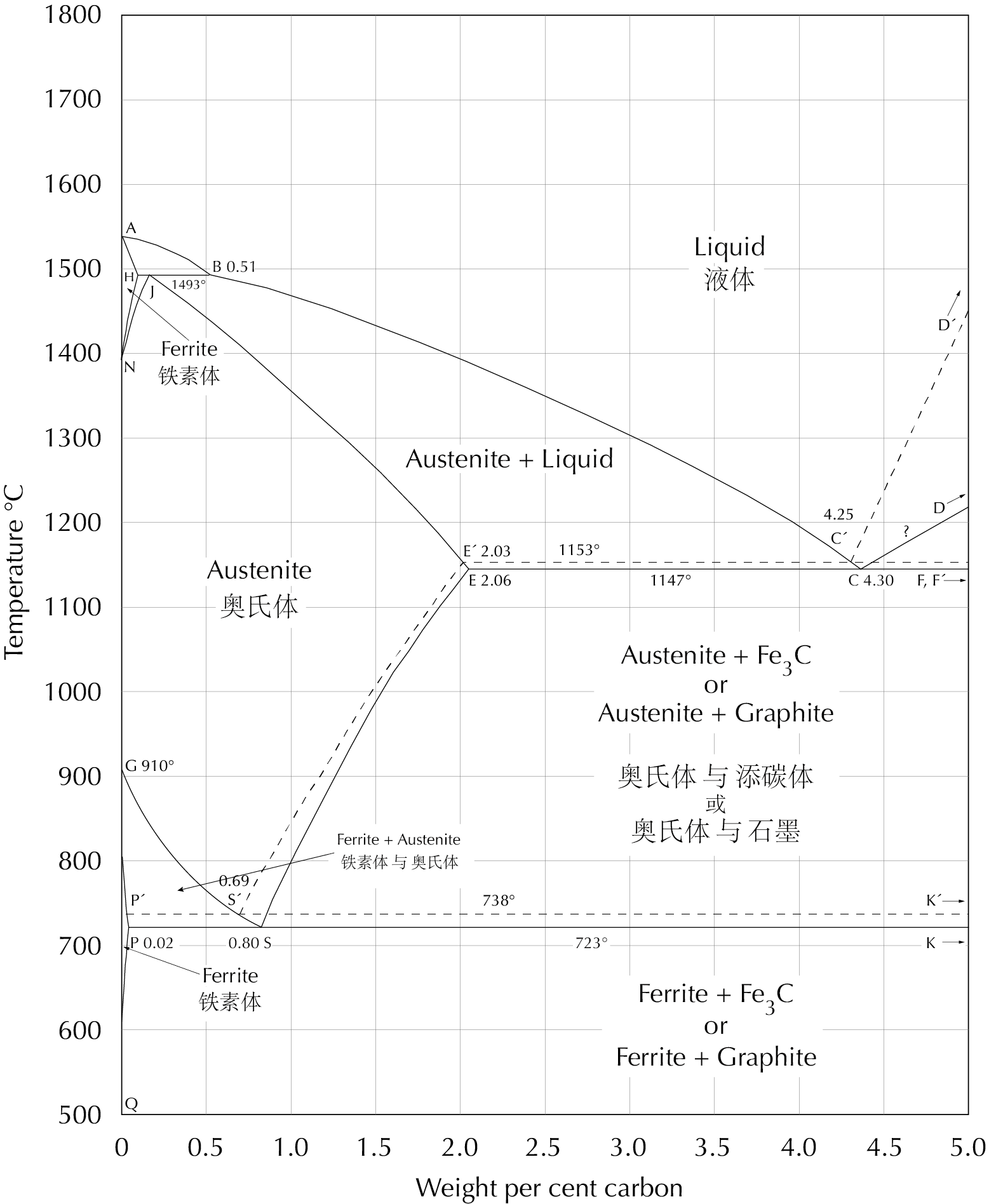
The liquidus line (ABCD or ABC′D′) in the iron-carbon phase diagram, seen here, shows that the melting temperature of iron falls with increasing carbon content. At 3–4% carbon the liquidus temperature is low enough to make practical casting possible, and therefore such alloys are called cast iron. While temperatures sufficient to melt steel were sometimes obtained in ancient times, ceramics that could withstand such high temperatures were not developed before the 18th century, in Britain. Without these, casting steel was not a practical possibility.

The iron-carbon phase diagram, which gives the atomic state of iron–carbon alloys at different carbon contents and temperatures (after Hansen 1958: 354). Students of archaeometallurgy will find it useful to print this diagram out and keep it for ready reference.
Iron that contains so much carbon is brittle. For most types of weapon or implement one would prefer to use steel, and it is only the low cost of cast iron which leads to its use in such applications. In ancient China we find that most iron weapons were made of wrought iron or steel while most iron implements were made of cast iron (Wagner 1993: 336; 2008: 1–2, 169–170); it seems that for weapons, high performance was essential, while for implements, cost was a more important factor.
In a pre-modern technological context, foundry methods are much cheaper than smithy methods for producing any metal product. In ancient China the use of cast iron made possible the widespread use of iron implements of all kinds from the third century B.C. onward, and also made possible the extravagant use of iron in the sixteen-ton ‘iron wall’ of the tomb of Dou Wan 窦绾 in Mancheng 满城, Hebei. Foundrywork also lends itself to geographically concentrated mass production, and its use in ancient China was probably one of the factors that encouraged the introduction, in 117 B.C., of the Han state monopoly of the iron industry.
 |
 |
 |
The outer wall of the tomb of Dou Wan, who died in the late second century BCE; and the casting runner of the “iron wall” cast in place behind it (Mancheng 1980, 1: 216, 218, 220, 2, pl. 154, 155.1). The iron wall was 4 m high, 3.3 m wide at the bottom, 4 m wide at the widest point, and 14 cm thick. The amount of iron used would seem to be about 16 tons.
Right: Vertical section through the “iron wall” . 1. Bricks. 2. Iron cast in place. 3. Straw-tempered clay. 4. Loess soil. 5. Unfired bricks. 6. Iron runner. 7. Stones. 8. Ashes.
In taking advantage of the low cost of cast iron there are various ways of dealing with the problem of its brittleness:
1. There is a whole class of artefacts in which the brittleness of cast iron is not a serious problem, for example vessels and parts of vessels ; shafts of crossbow-bolts; and decorative objects such as belt-hooks.
2. Careful design of an implement can reduce the danger of breakage despite the brittleness of the material. Appropriate design can also make breakage less expensive when it does occur, as in the ploughshare shown here: the edge, which is the part most subject to damage, is protected by a small V-shaped cap which when damaged can be replaced quickly and cheaply and thereafter recycled.
 |
 |
 |
 |
Mouldboard, ploughshare, and V-shaped cap found at Wangxiangcun in Liquan County 禮泉縣王相村, Shaanxi (Li Changqing & He Hannan 1966, pl. 3.3–6). a. The three artefacts. The cap is rusted fast to the ploughshare. Ploughshare 23.3 × 28 × 8.6 cm, mouldboard 22 × 23 cm. On the underside of the mouldboard are two lugs for tying with cord and a peg which fits precisely into the hole in the ploughshare. b–d. Three views of the artefacts when fitted together.
3. Careful control of the cast iron alloy composition and the melting and casting procedures can hold the brittleness of the casting to an acceptable limit. We shall see below that in ancient Chinese iron foundries efforts seem to have been made in some cases to cast implements ‘grey’ rather than ‘white’, thus obtaining a less brittle product, but more sophisticated techniques of this kind seem not to have been used.
4. Subjecting a casting to a lengthy heat treatment can significantly improve its mechanical properties. The result is called malleable cast iron. In modern practice the heat treatment is typically for a period of a day or two at a temperature in the range 900–1000 °C. The purpose may be a tougher casting, or one with a soft and easily machinable surface, or a combination of both. The technical reasons why the process works, and how its use can be recognized in the microstructures of artefacts,will be discussed below. The important matter to note here is that malleable cast iron was widely used in China as early as the fourth century B.C. It was used both for implements and for decorative objects. Until recently the latest malleable cast iron objects known in China were from the fourth century CE, and Chinese historians believed that the technique dropped out of use and was forgotten by the Tang period (e.g. Hua Jueming 1982a: 17–19). Later studies, however, have revealed several artefacts of malleable cast iron from as late as the ninth century (Du Fuyun 1991: 275–276, table 2, item nos. 14, 17, 28, 29, 34, 36, 37). There is also evidence that in both China and Japan a traditional technique for producing malleable cast iron was used to some extent as late as the eighteenth and nineteenth centuries (Wagner 1989: 8–11; 2008: 359–361). The modern process was reintroduced from the West in the early twentieth century.
White and grey cast iron
When iron has been melted and poured into a mould, it solidifies as either white or grey cast iron. These terms come from the colour of the fracture surface when the iron is broken; the colours are different because the microstructures are different. As early as 1722, Réaumur gave a very clear description of the two types (tr. Sisco & Smith 1956: 257–270): White cast iron (baikou zhutie 白口铸铁) is extremely hard and cannot be filed or chiseled. Since nearly all iron castings must be finished after they are taken from the mould, white cast iron was not a very useful material. Grey cast iron (huikou zhutie 灰口铸铁) is soft, and can be filed and chiseled, but the process is difficult to control, and the tool nearly always removes too much material. Grey cast iron could therefore (in 1722) be used only for coarse castings such as cooking pots and cannons. Both white and grey cast iron are brittle, and can break like glass when struck with a hammer. Réaumur seems never to have considered the possibility of casting implements of any kind of cast iron.
The technical explanation of the properties of white and grey cast iron came later, with better microscopes and with a better understanding of the role of carbon in iron. The carbon in white cast iron is in chemical combination with iron in cementite (iron carbide, Fe3C). A white cast iron with 4% carbon is 60% cementite. Cementite is extremely hard, harder than quartz, and this is why white cast iron is so hard.
In grey cast iron the carbon is in the form of microscopic graphite flakes, and it is these which cause a fractured surface to appear grey. Graphite is very light (2.2 g/cm3 vs 7.9 g/cm3for iron), and a grey cast iron with 4% carbon by weight has up to 13% graphite by volume. Graphite comes close to being the softest mineral known; in comparison with iron it has no strength at all. The microscopic flakes act therefore as empty internal cracks in the iron. It is these cracks which make grey cast iron brittle, and they also cause the iron to spall when it is filed or chiseled.
Réaumur, using the concepts of the chemistry of his time, explained the difference between white and grey cast iron as being due to differences in their content of ‘earthy matter’; but it confused the issue for him that the thickness of the casting also plays a role. As he notes, thin castings have a greater tendency to solidify white than thick castings.
We know today that solidification of cast iron as white or grey depends on the interaction of two factors, the chemical composition of the iron (especially the silicon content) and the cooling rate in the mould. High silicon content and slow cooling rate encourage solidification as grey cast iron, while low silicon content and fast cooling rate encourage solidification as white cast iron. What Réaumur interpreted as ‘earthy matter’ in his observations was various silicon–iron–oxygen compounds in slag; and thin castings cool more quickly in the mould than thicker castings (see Sisco & Smith 1956: 261, fn.).
The explanation of these phenomena lies in the fact that there are actually two related but distinct iron–carbon phase systems, the metastable iron–cementite system and the stable iron–graphite system. In the iron-carbon phase diagram (above), the stable system is shown with broken lines, the metastable system with solid lines. At low carbon contents the metastable system is very stable, and graphite is very rarely seen in steel; but in cast iron both systems are important. White cast iron is cast iron which has solidified according to the metastable system, grey cast iron according to the stable system.
The gaps between the solid lines in the phase diagram and the corresponding broken lines are important here. Slow cooling means more time within these gaps, and therefore more time for solidification as grey cast iron. The width of the gaps increases with increasing silicon content (Heine 1986, esp. figs. 3–4, p. 394), and this is likely to be one reason why higher silicon content encourages solidification as grey cast iron. But the metallurgy of cast iron is even today a very empirical subject, and we lack sure theoretical explanations for this and many other important phenomena (see e.g. Levi & Stamenov 1967).

‘The Maurer diagram’, redrawn and translated from German. A century ago, Eduard Maurer (1924) produced this diagram to show how the solidification of cast iron is affected by carbon and silicon contents. It is based on some rather uncertain theoretical considerations, together with a large body of experimental results. It appears still to be accepted as aproximately correct for fairly thick castings cast in air-dried sand moulds (e.g. Buchwald 2008: 306–307). (See also Murer & Holtzhaussen 1927.)
It can be seen that in the region of most interest in Chinese archaeometallurgy, with 0–0.5% Si, 3.5–4% C, the solidification state of the casting is very uncertain. Small variations in the content of these and other alloying elements can have large effects on the way the iron solidifies. And none of Maurer’s experimental data was in this region.
We need new experimental studies of this problem using the parameters typically found in ancient Chinese cast iron artefacts: fairly thin, with low silicon and other alloying elements, cast in ceramic or iron moulds.
Cast iron is never a simple alloy of iron and carbon. Except in occasional laboratory experiments, cast iron always contains significant amounts of silicon, phosphorus, sulphur, and manganese. Other alloying elements are usually present as well, either intentionally added or incidentally present. All of these alloying elements have effects, and some of the effects are quite surprising. We have just seen one of the effects of silicon. Either sulphur or manganese alone encourages solidification according to the stable system, but if both are present in the proper proportions they combine as MnS, which in moderate quantities has no significant effect. Some other effects of alloying elements in various contexts will be mentioned in passing further below.
White cast iron
White cast iron is used today in a number of applications in which abrasion resistance and high compression strength are important. S. C. Massari (1938: 217, 233) gives as examples railroad car wheels, the wearing parts of crushing machines, bearings, sprockets, ploughshares, and mouldboards. It is much more important, however, in the production of malleable cast iron, to be discussed below. In a pre-modern context white cast iron could have been useful in a much wider range of applications.
Among Chinese artefacts there are many of white cast iron, for example axle collars, mattock-caps, and some parts of moulds. Axle-collars and mattock-caps would be subject in use to considerable abrasion, and white cast iron may be a very good material for these, though we shall see below that many ancient Chinese mattock-heads have been found to be of malleable cast iron. A ploughshare and an axle-collar were found to be mottled cast iron (bandian zhutie 斑点铸铁 or makou zhutie 麻口铸铁), i.e. white cast iron with some graphite flakes in the structure. Since these artefacts require extreme abrasion resistance it is possible that it would have been better to have a pure white structure here. For the iron moulds a grey structure would probably have been more appropriate than the white structure found here, and it will be seen below that several other mould parts have been found to be of grey cast iron.
  |
 |
 
|
|---|---|---|
| Fragment of an axle-collar from Sandaohao 三道壕 (Hua Jueming et al.1960: 76, pl. 2.6). Dimensions are given in mm. | Fracture section of a cast-iron mould-core from Xinglong 兴隆 (Hua Jueming et al. 1960, pl. 2.1). Note shrinkage cavity. | Mattock-cap (jue 镢) from Mancheng 满城 (Mancheng 1980: 281, pl. 197.1). |
 |
 |
 |
| Microstructure of the axle-collar fragment (Hua Jueming et al. 1960, pl. 3.1). Scale bar 50 µm. 100% ledeburite, with a gas hole. | Microstructure of the mould-core (Hua Jueming et al. 1960, pl. 2.2). Scale bar 200 µm. Ledeburite + proeutectic cementite. | Microstructure of a similar mattock-cap from Mancheng (Mancheng 1980, pl. 261.1). Scale bar 50 µm. Ledeburite + proeutectic cementite. |
We shall now look briefly at some of the possible microstructures of white cast iron and how they come about. Consider first, in the iron–carbon phase diagram, what happens to an iron–carbon alloy with the eutectic (gongjing 共晶) composition, 4.3% carbon, starting in the molten state and cooling through 1147°C, which is the eutectic temperature (gongjing wendu 共晶温度). We assume that cooling is sufficiently quick that only the metastable iron–cementite system (the solid lines in the diagram above) need be considered. When the point C, the eutectic point (gongjing dian 共晶点), is reached, the liquid must transform to a solid which consists of two phases, austenite and cementite. The eutectic structure (gongjing zuzhi 共晶组织) formed in this transformation resembles the structure shown in the first figure above, but all of the micrographs here show the structure of the iron after a number of further transformations have taken place. During the cooling between 1147°C and 723°C, the maximum carbon content of the austenite decreases (see the line ES), and more cementite precipitates from the austenite. At 723°C the austenite transforms to pearlite. (In the further cooling from 723°C to ambient temperature no significant changes occur.) The final result of all these transformations is a microstructure like that of the axle-collar fragment, above. This structure is called ledeburite (laishiti 莱氏体). The black areas in these black-and-white photographs are pearlite and the white areas are cementite.

Dendrites

Microstructure of an iron mould-section from Mancheng 满城 (Mancheng 1980, pl. 253.2). Scale bar 100 µm. Ledeburite + dendritic pearlite.
Next we consider an iron–carbon alloy with 3.5% carbon. This is an example of a hypoeutectic (yagongjing 亚共晶) composition, i.e. one with less than 4.3% carbon. At 1300°C it is molten. As it cools, when the temperature reaches the liquidus line BC at ca. 1250°C, austenite begins to precipitate from the melt. This austenite takes a symmetric branching form and is therefore referred to as dendritic (shuzhizhuang 树枝状) (from the Greek dendros, ‘tree’). When the iron has cooled to just above 1147°C it consists of ca. 36% dendritic austenite with 2.06% carbon and ca. 64% liquid with 4.3% carbon. Just under this temperature the liquid transforms to ledeburite as described above. During the further cooling to 723°C more cementite precipitates from the austenite, and just under 723°C the austenite transforms to pearlite. The resulting structure can be seen here on the right. The dendritic pearlite (formed from what was left of the dendritic austenite formed above 1147°C) is seen in a two-dimensional section through the complex three-dimensional structure.
Readers may now wish to work through the same exercise for an iron–carbon alloy of hypereutectic (guogongjing 过共晶) composition, i.e. with more than 4.3% carbon. When this is cooled through the liquidus line CD, cementite precipitates from the melt; however not in dendritic form but in the form of microscopic plates. These can be seen in the micrographs of a mould-core and a mattock-cap further above.
A special problem with the use of white cast iron is that it is rather difficult to cast. The shrinkage of white cast iron on solidification is in the range 4–5.5% by volume, and this makes it one of the most difficult to cast of all the metals commonly cast in modern industry; in this regard only steel is worse. It also has a strong tendency to evolve gases from the melt. These two factors lead to shrinkage cavities (suokong 缩孔) and gas holes (qipao 气泡) in the castings; examples are the axle-collar and the mould-core shown further above. Furthermore both the shrinkage which takes place on solidification and that which takes place in the solid state when the casting cools to ambient temperature cause stresses in the casting; the brittleness of white cast iron means that these stresses may lead to cracks, as can be seen for example in the mattock-cap shown above.
Shrinkage cavities and gas holes reduce to some extent the strength of a casting, but can often be tolerated. It is not clear whether the cracks in the mattock-cap rendered it unfit for use. It does not appear so, but we cannot be sure, since the artefact was found in a pile of scrap rather than in a context of use.
Grey cast iron

Microstructure of an iron mould from Mianchi (Wenwu 1976.8: 54). Scale bar 200 µm. Ferrite + graphite.
Grey cast iron is by far the most widely used form of cast iron in modern industry. Its low cost, excellent casting properties, and reasonably good mechanical properties make it the material of choice for a wide variety of applications. In modern industry, grey cast iron generally has about 2% silicon. Analyses of ancient Chinese cast iron artefacts show very low silicon contents, and cast iron with such low silicon normally solidifies white (see e.g. table 7.1 in Wagner 1993: 450–456; table 6 in the translation, Wagner 2018: 221–227). To cause it to solidify as grey cast iron requires elaborate techniques to assure that it cools extremely slowly in the mould. It is therefore not surprising that grey cast iron was seldom used in ancient China. This ploughshare-cap mould from Mianchi is the most interesting of these, for we also know its chemical composition, 2.31% carbon and 0.21% silicon, yet it is grey-cast. This artefact was probably cast in a pre-heated massive ceramic mould and allowed to cool very slowly, as was observed by a traveller in Guangdong in the 19th century (donwagner.dk/wok/wok.html).
Let us now look briefly at the microstructures of grey cast iron and how they come about. Consider as an example an iron with very low silicon content (perhaps 0.2%), so that its phase diagram is approximately that shown above (which is actually for the unrealistic case of zero silicon), and with 3.5% carbon. Above 1250°C this iron is molten. As it cools, when the temperature reaches the liquidus line at ca. 1250°C, dendritic austenite begins to form. Just above 1153°C the iron consists of ca. 34% austenite with 2.03% carbon and ca. 66% liquid iron with 4.25% carbon. Just under 1153°C, but still above 1147°C, graphite can form but cementite cannot yet form. If the iron remains long enough at a temperature within this gap, the liquid iron will transform to a solid structure composed of ca. 98% austenite (still with 2.03% carbon) and ca. 2% (by weight; ca. 7% by volume) graphite, which is 100% carbon. The most common shape of graphite formed in this way is shown in the sketch below; many other shapes are possible. During slow cooling through the range 1153 – 738°C more graphite precipitates from the austenite, and just above 738°C the iron consists of ca. 97% austenite with 0.69% carbon and ca. 3% graphite (10% by volume). In the gap between 738°C and 723°C the austenite can transform to ferrite + graphite; below 723°C whatever is left of the austenite transforms to pearlite (ferrite + cementite). In the remaining cooling, down to ambient temperature, no further significant changes occur.

Reconstruction of the three-dimensional shape of graphite in grey cast iron (Merchant 1961: 82).
Typical microstructures of grey cast iron after polishing can be seen in the illustration above from Mianchi and the series below from the Chengdu bridge pier. The bridge pier is so large that it must have cooled very slowly in the mould. The black streaks are graphite flakes, seen in a two-dimensional section through a three-dimensional structure that resembles the sketch shown here on the left.
 |
 |
 |
 |
 |
| Unetched | Etched with nital. | |||
Four metallographs showing the microstructure of a cast-iron bridge pier, dated 96 BCE, found near Chengdu, Sichuan (Li Yingfu et al. 2015; 2016). The arrow shows where the sample was taken.
Cast iron moulds for casting iron are subject to extreme stress when they are suddenly heated by the white-hot molten iron, for the same reason that a glass tumbler may break if boiling water is poured into it. After cooling it may also be necessary to strike the mould a hard blow in order to free the casting. Great strength or hardness is not required here, but rather elasticity or ductility. Among cast iron moulds that have been examined, some are white cast iron, some pearlitic grey cast iron, and some ferritic grey cast iron. It seems likely that these last were the best, and the fact that great trouble was needed to produce this structure suggests that the effect of cooling rate on the mechanical properties of an iron casting was well understood empirically by the ancient Chinese ironfounders. Moulds seem never to have been made of malleable cast iron. This was perhaps because malleable castings tend to warp slightly during the anneal; it was important that the cast-iron mould-parts could fit perfectly together.
Mottled cast iron
Some examples are known of artefacts of ‘mottled’ cast iron, which has cooled at such a rate that both graphite and cementite are formed when the temperature is in the neighbourhood of the eutectic temperatures (1153°C and 1147°C). There are very few, if any, applications in which such a structure would be preferred, though there are many in which it would be acceptable. These artefacts are probably examples of imperfect control of the solidification rate. Below are micrographs at three magnifications of a sample of mottled cast iron, from the classic German compendium Atlas metallographicus (Hanemann & Schrader 1936, pl. 415, 416, 427).
 |
 |
 |
| Microstructure of a sample of hypoeutectic white cast iron with slight mottling. Scale bar 0.5 mm. Analysis C 3.67%, Si 0.81%, Mn 0.37%,P 0.47%, S 0.06%. Ledeburite + dendritic pearlite + graphite flakes. | The same at a higher magnification. The black blobs are ‘nests’ of flake graphite and overetched pearlite. | The same at even higher magnification, lightly etched, showing graphite flakes in pearlite. |
Graphite shape
The shape of the graphite flakes has considerable effect on the mechanical properties of grey cast iron. In general, rounded forms are better than sharp forms. A great deal of research has been done in the twentieth century on ways of improving graphite shape in grey castings. It does not appear that any of the techniques developed have been used in ancient China, so we need not say much about them here, but one word of warning is required. In the late 1940’s Henton Morrogh in Birmingham developed what could be thought of as the ultimate grey cast iron. Cast iron alloyed with magnesium and cerium can solidify with its carbon in the form of microscopic graphite spheroids, or ‘spherulites’ (Morrogh & Williams 1948). This is of course the most rounded form possible, and the mechanical properties of this iron are very good indeed. It may for many purposes be considered to be a superior kind of grey cast iron, though it is so different in mechanical properties from ordinary grey cast iron that it is always referred to as ‘ductile cast iron’ or ‘SG-iron’ (for ‘spherulitic graphite’). Graphite with this spherulitic form has also been found in some ancient Chinese malleable cast iron artefacts, and much has been made of these artefacts as an anticipation of Morrogh’s invention (e.g. Guan Hongye & Hua Jueming 1983; cf. Parkes 1983). The question of how this structure was produced has attracted considerable attention, and it is still something of a mystery, but one thing is very certain: it was not produced by alloying with magnesium or cerium, and therefore has no relation to Morrogh’s invention. Nor has it been proven that the ancient artefacts in question had better mechanical properties than other ancient Chinese malleable cast iron artefacts, for the strength and toughness may very well be limited by other factors. Finally, no proof has been offered that the ancient founders intentionally produced this structure in preference to other structures. I have done some experiments to investigate aspects of this problem (Wagner 1986/2021).
Shrinkage
The problem of shrinkage upon solidification of white cast iron has been mentioned above. In grey cast iron the precipitation of graphite, which is much less dense than iron, compensates rather closely for this shrinkage; this fact is one reason why grey cast iron is the easiest to cast of the common industrial metals. In modern grey cast iron the high silicon content means in addition that much less gas is evolved from the melt, so that gas-holes are much less of a problem; but this factor was of course not operative in the low-silicon cast iron of ancient China.
Malleable cast iron
On the metallurgy of malleable cast iron, early modern studies tend to be most relevant to an understanding of ancient artefacts. A few examples are Rott 1881; Schwartz 1922; Yan Guocui & Wu Bingrong 1985; Schüz & Stotz 1930; and Guédras 1927–28.
Note that some early writers called whiteheart and blackheart malleable cast iron ‘European’ and ‘American’ respectively.
As has already been mentioned, annealing (heat treating) a white cast iron object at a high temperature for a period of days can significantly improve its properties. Two quite different processes operate to bring about this effect, decarburization (tuotan 脱碳) and graphitization (shimohua 石墨化). The resulting product is called malleable cast iron (renxing zhutie 韧性铸铁, keduan zhutie 可锻铸铁, or matie 玛铁). Some American writers call it malleable iron, but this term is ambiguous, and I never use it.
If the furnace atmosphere during the anneal is slightly oxidizing, the carbon in the iron is burned away at the surface. In the course of a few days all or most of the carbon in the casting can diffuse to the surface and be burned away, leaving a decarburized iron casting whose carbon content corresponds to that of steel or even wrought iron.
On the other hand another process may operate. The iron may ‘graphitize’; that is, the cementite (iron carbide, Fe3C) in the iron can decompose and precipitate as graphite (Fe3C → 3Fe + C). It happens that the microscopic graphite ‘nodules’ precipitated in this process normally have a much more rounded shape than the flakes in grey cast iron; graphitized white cast iron is therefore much more tough than grey cast iron.
In modern industry nearly all malleable cast iron is heat-treated in such a way that, of these two processes, only graphitization is operative. Until recently, however, the processes were usually carried out in such a way that both were operative, with one or the other dominant. If the primary effect of the heat treatment is to decarburize the casting, the product is called whiteheart (baixin 白心) malleable cast iron; if the primary effect is graphitization, the product is called blackheart (heixin 黑心) malleable cast iron. (The names come from the appearance of the fracture in older practice.)
Annealing techniques
In industry in the early 20th century the heat treatment of castings to produce malleable cast iron was normally as follows. The castings were sealed, together with a packing material, in cast-iron, steel, or ceramic ‘annealing pots’ (or ‘saggars’, shaopen 烧盆). The packing could be a chemically neutral material such as sand or crushed slag, in which case its only purpose was to provide mechanical support for the castings, which might tend to warp or droop at the high temperatures used. It might on the other hand be an oxidizing material, such as iron oxide, assuring a slightly oxidizing atmosphere in the annealing pot to decarburize the iron. Many tons of castings were packed in annealing pots and the pots stacked up in a large annealing furnace, which usually was fired with cheap coal, sometimes with gas.
It was realized very early that the use of these heavy pots, together with the packing material, was wasteful of both labour and fuel, and that much could be saved if the pots were eliminated. Charles James (1900) described the annealing of castings directly exposed to the furnace combustion gases, and stated that this could be useful, though it did involve some scaling (surface oxidation) of the castings. Annealing without annealing pots was seldom practised, however, until World War II, when the ‘gaseous process’ was developed in parallel efforts in Germany and Britain. The fuel used was gas; this allowed better control of the furnace atmosphere, which could be precisely adjusted to be neutral or oxidizing as desired; and also better temperature control, so that warping of the castings became a much less serious problem. The use of the gaseous process led to a great saving in time and fuel, as is shown for example by a survey (Hernandez 1967) of malleable foundries in the United States using both processes. The foundries still using annealing pots reported total annealing times of 68–201 hours, those using the gaseous process 12–52 hours.
J. J. Rein's description of a traditional Japanese process of malleablizing annealing
More surprising than the inlaid work on the forged iron armour and the weapons, is its direct employment on cast-iron Tetsu-bin [鐵瓶], vases and other articles. As is well known, the cast iron cannot, on account of its hardness and brittleness, be worked with the hammer, chisel and burin. The way in which these properties are lessened by the reduction of the carboniferous contents has been observed by Lehmann and Wagoner in Kyoto. It is a peculiar decarburising process, by which the kettle or pot receives a structure like to that of soft iron or steel, and can then be treated in the same way as in the Zogan [象眼]-work on forged iron.
The process of decarburisation of the surface is called yakeru [燒ける] (to burn), and is performed with primitive apparatus. Old damaged rice kettles out of which the bottom has been knocked serve as ovens. These are plastered over on the inside with a fire clay (Oka-saki-tsuchie [岡崎土] and sand mixed in equal parts), so that a cylindrical space of the size of the hole in the bottom, remains open. The Kama [釜, 窯] or kettle thus prepared, is turned over upon a thick plate or slab, three or four centimeters thick, made out of the same fire-proof material, which serves as a grate, and is perforated like a sieve for this purpose. In order to give this plate greater firmness, it is bound around with an iron band. The holes have a width of about 1–5 centimeters. In order to give the air free play, several stones are laid under the edge of the slab. Then the Tetsu-bin to be burned, whose outside has been carefully cleaned beforehand from dust and sand, is placed in the Kama, directly on the grate.
The difference in size between the Kama and the Tetsu-bin must be such that a space of at least five centimeters remains open around the latter. This open space is then filled with the best charcoal in pieces the size of a nut, till the Kama is filled to the rim, when the coal is kindled.
In order to increase the draught, two or three Kamas filled in the same way are set one over the other, forming a kind of chimney. When the coals have ceased glowing, others are put in, and when the second instalment is burned out, the Tetsu-bin are taken out and turned upside down (with the opening underneath), set again In the Kama and burned twice in this position. Under favourable circumstances, the surface is now sufficiently soft and tough, as is ascertained with a file. It is often the case that the furnace must be heated ten times. After the cooling the decorations are then carved as in forged iron, without danger of breaking the edges, or recoil of the burin.
(Rein 1886: 518–520; translation Rein 1889: 434–435).
There is evidence for the use in ancient China of at least two different techniques in annealing iron castings: in a packing of iron ore in a large reverberatory furnace, and without packing in a furnace very like a pottery kiln. Many other techniques are known which could have been used. For example J. J. Rein in 1886 described a traditional Japanese method of decarburizing cast-iron tea-kettles by embedding the casting in burning charcoal. In Britain in the 18th century, malleable cast iron nails seem sometimes to have been made by casting a nail and then taking it red-hot from the mould and holding it in a blast of air (Smith 1968a: 268–270). The combustion of the carbon in the iron, as well as some of the iron itself, could keep it at the necessary temperature.
Graphitization: Blackheart malleable cast iron
Consider now, on the iron–carbon phase diagram, a sample of white cast iron with 3.5% carbon, heated to 950°C. After a fairly short time (less than a half hour) the metastable equilibrium is reached; the iron then consists of ca. 60% austenite with ca. 1.4% carbon and ca. 40% cementite with 6.7% carbon. At high temperatures the metastable iron–cementite system is not as stable as at room temperature, and cementite can break down to iron + graphite (Fe3C → 3Fe + C). The graphite precipitated in this process takes the form of nodules which are very different in shape from the flakes in grey cast iron; examples are shown below. Equilibrium in the stable iron–graphite system may be reached in a matter of hours or days, depending on a number of factors, especially the content of alloying elements such as silicon and sulphur. Silicon accelerates graphitization and sulphur retards it.
 |
  |
  |
  |
|---|---|---|---|
| Implement-cap from Changsha (Lu Da 1966, pl. 2.3). | Spade-head from Mancheng (Mancheng 1980: 281, pl. 196.3). | Fragment of a mattock-cap (jue 镢) from Mancheng (Mancheng 1980: 112, pl. 72.1). | Hexagonal hoe-head from Yixian (Liu Shishu 1975: 233, pl. 4.9). |
 |
 |
 |
 |
| Microstructure of the implement-cap (Lu Da 1966, pl. 3.7). Scale bar 250 µm. | Microstructure of a similar spade-head from Mancheng (Mancheng 1980, pl. 252.4). Scale bar 100 µm. Ferrite, pearlite, and compact nodular graphite. | Microstructure of the mattock-cap from Mancheng (Mancheng 1980, pl. 252.5). Scale bar 100 µm. Graphite and spheroidized cementite in a ferrite matrix. | Microstructure of the hexagonal hoe-head from Yixian (Li Zhong 1975, pl. 1.4). Scale bar 200 µm. |
At stable equilibrium at 950°C the iron consists of ca. 98% austenite with ca. 1.4% carbon and ca. 2% graphite (which is 100% carbon). As the sample is slowly cooled from this temperature to just above 738°C the solubility of carbon in austenite decreases (see the line S"E" in the iron–carbon phase diagram), and more graphite therefore precipitates; the existing graphite nodules grow larger. Just above 738°C the iron consists of ca. 97% austenite with 0.69% carbon and ca. 3% graphite. While the temperature is between 738°C and 723°C the rest of the austenite can transform to ferrite + graphite, leaving a microstructure which is composed of graphite nodules in a matrix of ferrite. If cooling through this temperature range is too fast for the precipitation of more graphite, the austenite will, when the temperature falls under 723°C, transform to pearlite, leaving a microstructure which consists of graphite nodules in a matrix of pearlite or pearlite + ferrite, as seen for example in the implement-cap from Changsha, shown above.
What is important about the graphite structures obtained by annealing white cast iron is that the shape of the graphite nodules is much more rounded than that of flake graphite. The graphite therefore has much less influence on the mechanical properties of the iron than flake graphite does, and blackheart malleable cast iron has for example a much higher tensile strength than grey cast iron.
Decarburization: Whiteheart malleable cast iron.

Equilibrium conditions for certain reactions which are important in ferrous metallurgy. The vertical axis gives the ratio of partial pressures of carbon monoxide (CO) and carbon dioxide (CO2) in the furnace atmosphere. When furnace conditions are above a particular line, the corresponding reaction goes to the right; if below, to the left. Curve A and the curves between A and C (except B) are calculated with the assumption that the atmosphere contains ca. 79% nitrogen. Reproduced from Wagner 2008: 92, Figure 41.
The calculations on which this diagram is based are here.
Whether the atmosphere in a furnace or annealing pot is oxidizing or reducing depends on the temperature and the content of carbon dioxide and carbon monoxide. (Other chemically active gases such as hydrogen and steam can be assumed to be absent in a pre-modern context.) The figure here on the right shows the equilibrium conditions for the reactions which are relevant to present purposes. The horizontal axis gives the temperature, and the vertical axis gives the ratio of partial pressures of carbon dioxide (CO2) and carbon monoxide (CO) in the atmosphere of a furnace or annealing pot. (The ‘partial pressures’ may be thought of simply as proportions by volume.) In the annealing of an object of white cast iron, if the atmosphere and temperature correspond to a point on or just below the line C and to the right of the line D, the equilibrium carbon content at the surface of the iron will be close to zero and carbon will be burned away at the surface. As the carbon content at the surface decreases, carbon in the interior of the casting will diffuse to the surface and likewise be burned away. At any point above the line C, iron can be burned as well; this is of course undesirable. In the ‘gaseous process’ for annealing whiteheart malleable cast iron, the carbon dioxide – carbon monoxide ratio can be measured (or estimated from the flame colour) and adjusted as required. In the older process, using closed annealing pots, the castings were packed in the pots together with iron oxide, usually haematite ore or rolling-mill scale or the like; in all cases with a large proportion of Fe2O3 (Rott 1881: 346; Guédras 1927: 447; Giessereipraxis 1938). It was important to use a mixture of new and used packing material, 1 part new to 3–5 parts used (i.e. previously used as a packing material). The reactions which take place in the annealing pot are as follows. In the first few minutes of the anneal, all of the oxygen present reacts with carbon in the iron castings to produce carbon monoxide, CO. Thereafter the following reactions dominate:
3 Fe2O3 + CO → 2 Fe3O4 + CO2
C (in Fe) + CO2 → 2 CO
That is, CO is oxidized to CO2 by the iron oxide and this CO2 then oxidizes the carbon in the iron, itself being reduced to CO which can again react with iron oxide. The equilibrium atmosphere in the annealing pot will then lie somewhere between the lines A and D in the diagram, which give equilibrium conditions for the two reactions above. Exactly where in this area it will lie depends on the relative reaction rates, and cannot be calculated. The use of a mixture of new and used iron oxide as the packing material appears to be an empirically developed method for obtaining an atmosphere near the line C; that is, an atmosphere which decarburizes the castings but does not burn them to a significant extent. Presumably at least two factors lead to this result: iron oxide which has been used before has a larger proportion of Fe3O4, and it can also be expected to be less reactive than new iron oxide, so that the first reaction above proceeds more slowly.

Carbon content vs. depth in a whiteheart malleable cast iron product annealed at a temperature in the range 910°C < T < 1147°C. CI is the carbon content of the original casting, typically around 4%. Cγ2 is the maximum carbon content of austenite at temperature T. If T = 950°C, this is about 1.3%.
If the annealing temperature is above 910°C, the distribution of carbon content from the surface to the core will be as graphed here on the right. A clear example is the implement-cap whose microstructure is shown below. There is a ledeburitic core, a sharp border between this and a layer of pearlite, a gradual increase in the amount of ferrite toward the surface, and close to 100% ferrite at the surface. The implement-cap from Luoyang, shown further below, was badly corroded, but shows much the same carbon distribution.
 |
 |
 |
 |
 |
 |
|---|---|---|---|---|---|
| Implement-cap from Shijiazhuang (Hua Jueming et al. 1960, pl. 1.1–6). It was sectioned at A–A. At A is a shrinkage cavity. | Outer layer | Intermediate layer | Inner layer | ||
| Microstructures at four points in the section of the implement-cap. All etched with 4% nital, scale bar 50 µm. | |||||
 |
 |
 |
| Implement-cap from Luoyang (Li Zhong 1975, pl. 1.1). | Microstructure at core, Scale bar 100 µm. | Microstructure near the surface. Scale bar 200 µm. |

Carbon content vs. depth in a whiteheart malleable cast iron product annealed at a low temperature, 723°C < T < 910°C. CI is the carbon content of the original casting, typically around 4%. Cγ1 and Cγ2 are the minimum and maximum carbon contents of austenite at temperature T;Cγ1 is the maximum carbon content of ferrite at T. If T = 800°C, Cα1 ≈ 0.01%, Cγ1 ≈ 0.3%, and Cγ2 ≈ 1%.
If on the other hand the temperature is in the range 723–910°C the carbon distribution will be as shown here on the right. Such low temperatures have never been used in modern whiteheart annealing, but the structure can be seen in the hexagonal hoe-head from Tonglüshan whose microstructure is shown below. This has a core of ledeburite, a surface layer of ferrite 1 mm thick, and a layer of pearlite 0.2 mm thick between these two. The ferrite grains are columnar; this indicates that they grew inward in the course of the anneal.
It should be noted that an anneal entirely in this temperature range is not the only way of obtaining this carbon distribution. The hoe-head could have been annealed at a much higher temperature, then cooled slowly through these temperatures while the atmosphere in the furnace or annealing pot remained oxidizing. I know of no way of distinguishing the two possibilities.
 |
 |
 |
| Fragment of a hexagonal hoe-head from Tonglüshan (Ye Jun 1975: 5). Thickness 0.22 cm at cutting edge, 0.3 cm at farther side. | Microstructure of the hoe-head fragment at point a. Scale bar 0.5 mm. | Magnified microstructure of the central band in the previous micrograph. Scale bar 200 µm. |
And a word of warning: Back in 1989 I published a theoretical method for determining the temperature and time of the annealing of a whiteheart malleable cast iron artefact, and I claimed that this hoe-head was annealed at 750°C for 12 days. Later Professor Hua Jueming 华觉明 pointed out to me that this is nonsense. His words were more polite, but this is what he meant. The calculation may possibly be mathematically correct – I have not had an opportunity to test it in a laboratory – but it assumes that the casting was raised to 750° very quickly, held at that exact temperature for 12 days, then cooled very quickly. In a modern laboratory that is difficult. In a pre-modern foundry it is impossible, and furthermore there would have been no reason to attempt it. I was very proud of my calculation, but it is useless for archaeometallurgists.
References
Buchwald, Vagn Fabritius. 2008. Iron, steel and cast iron before Bessemer: The slag-analytical method and the role of carbon and phosphorus (Historisk–filosofiske skrifter 32). Copenhagen: Det Kongelige Danske Videnskabernes Selskab.
Du Fuyun 杜茀云. 1991. ‘Yipi Sui Tang mu chutu tieqi de jinxiang jianding’ 一批随唐墓出土铁器的金相鉴定 (Metallographic examination of some iron artifacts from Sui- and Tang-period graves). Kaogu 考古 1991.3: 273–276 + pl. 7.
Giessereipraxis. 1938. ‘Glüh- und Packmittel für Temperguss’. Giessereipraxis 59.23/24: 226–229.
Guan Hongye 关洪野, and Hua Jueming 华觉明. 1983. ‘Research on Han Wei spheroidal-graphite cast iron’. Foundry trade journal international. Cf. Parkes 1983.
Guédras, M. 1927–28. ‘La fonte malléable’. La revue de fonderie moderne 25 mars 1927, 30–32; 10 avr., 58–61; 25 juin, 185–190; 10 juillet, 210–213; 25 sept., 375–376; 10 nov., 443–447; 10 janv. 1928, 7–14; 25 janv., 27–29.
Guyan, Walther Ulrich (ed.). 1967. Vita pro ferro: Festschrift für Robert Durrer zum 75. Geburtstag am 18. November 1965. Schaffhausen. n.d. [ca. 1967].
Hanemann, H. 1913. ‘Metallographische Untersuchung einiger altkeltischer und antiker Eisenfunde’. Internationale Zeitschrift für Metallographie 4.248–256.
Hansen, Max. 1958. Constitution of binary alloys. 2nd edn. New York: McGraw-Hill.
Heine, R. W. 1986. ‘The Fe–C–Si solidification diagram for cast irons’. Transactions of the American Foundrymen’s Society 94: 391–402.
Hernandez, Abelardo. 1967. ‘Analysis of survey on heat treatment practices used for annealing ferritic malleable castings’. Transactions of the American Foundrymen’s Society 75: 605–610.
Hua Jueming 华觉明. 1982a. ‘Han Wei gao qiangdu zhutie de tantao’ 汉魏高强度铸铁的探讨 (A discussion of the high-strength cast iron of the Han and Wei periods). Ziran kexueshi yanjiu 自然科学史研究 1.1: 1–20 + pl. 1–2.
Hua Jueming 华觉明, Yang Gen 杨根, and Liu Enzhu 刘恩珠. 1960. ‘Zhanguo Liang Han tieqi de jinxiangxue kaocha chubu baogao’ 战国两汉铁器的金相学考查初步报告 (Preliminary report on metallographic examination of some Warring States and Han period iron artifacts). Kaogu xuebao 考古 學報 (‘Acta archaeologia Sinica’) 1960.1: 73–88 + pl. 1–8.
James, Charles. 1900. ‘On the annealing of white cast iron’. Journal of the Franklin Institute 150.3: 227–235.
Levi, L. I., and S. D. Stamenov. 1967. ‘Features of eutectic crystallisation in the metastable Fe – Fe3C – Si system and Si segregation in white iron’. Russian castings production 1967.5: 221–224.
Li Changqing 李长庆, and He Hannan 何汉南. 1966. ‘Shǎnxi sheng faxian de Handai tie hua he bitu’ 陕西省发现的汉代铁铧和鐴土 (Han-period ploughshares and mouldboards discovered in Shaanxi). Wenwu 文物 1966.1: 19–26 + pl. 3–4.
Li Chunli 李春立, Liu Baicheng 柳百成, and Wu Dehai 吴德海. 1983. Zhutie shimo tupu – Guangxue yu saomiao dianzi xianwei zhaopian 铸铁石墨图谱 – 光学与扫描电子显微镜照片 (Atlas of cast-iron graphite: Optical and scanning electron micrographs). Beijing: Jixie Gongye Chubanshe.
Li Yingfu 李映福, Yang Sheng 杨盛, Ma Chunyan 马春燕, and Yu Jian 余建. 2015. ‘Sichuan Guanghan Shi’tingjiang Handai tie qiaodun de faxian ji xiangguan wenti yanjiu’ 四川广汉石亭江汉代铁桥墩的发现及相关问题研究. Kaogu 考古 2015.9: 101–113.
———. 2016. ‘A cast-iron bridge pier dated 96 BCE found in Sichuan, China’. Journal of the Historical Metallurgy Society 49.1: 26–36. Translated by Donald B. Wagner. Original Kaogu 考古 (‘Archaeology’), 2015.9: 101–113.
Li Zhong 李众. 1975. ‘Zhongguo fengjian shehui qianqi gangtie yelian jishu fazhan de tantao’ 中国封建社会前期钢铁冶炼技术发展的探讨. Kaogu xuebao 考古学报 1975.2: 1–22 + plates 1–6.
Liu Shishu 刘世枢. 1975. ‘Hebei Yixian Yanxiadu 44 hao muzang fajue baogao’ 河北易县燕下都 44 号墓发掘报告 (Excavation of grave no. M44 at the Yanxiadu site in Yixian County, Hebei). Kaogu 考古 1975.4: 228–240 + 243 + plates 3–5.
Lu Da 陆达. 1966. ‘Zhongguo gudai de yetie jishu’ 中国古代的冶铁技术 (‘Iron making in ancient China’). Jinshu xuebao 金属学报 (‘Acta metallurgica Sinica’) 9.1: 1–3 + pl. 1–4. English abstract p. 3. Full Chinese text + German translation, ‘Die uralte Technik der Eisenherstellung in China’, Guyan 1967: 63–70.
Mancheng. 1980. Mancheng Han mu fajue baogao 满城汉墓发掘报告 〔上 下〕 (‘Excavation of the Han tombs at Man-ch’êng’). (Zhongguo tianye kaogu baogao ji: Kaoguxue zhuankan, D.20 中国田野考古报告集•考古学专刊) Beijing: Wenwu Chubanshe.
Massari, S. C. 1938. ‘The properties and uses of chilled iron’. Proceedings of the American Society for Testing Metals 38: 217–234. Discussion, pp. 233–234.
Maurer, Eduard. 1924. ‘Über ein Gußeisendiagramm’. Kruppsche Monatshefte 5.7: 115–122.
———, and P. Holtzhaussen. 1927. ‘Das Gußeisendiagramm von Maurer bei verschiedenen Abkühlungsgeschwindigkeiten’. Stahl und Eisen 47.43: 1804–1813 + Tafel 20.
Merchant, Harish D. 1961. ‘Solidification, structure, and properties of gray iron’. Foundry, Nov.1961: 80–87.
Morrogh, H., and W. J. Williams. 1948. ‘The production of nodular graphite structures in cast iron’. Journal of the Iron and Steel Institute 158: 306–322.
Parkes, L. R. 1983. ‘S.-g. iron or not S.-g. iron?’. Foundry trade journal 27 Oct. 1983: 391–392. Comment on Guan Hongye & Hua Jueming 1983, repr. from The metallurgist and materials technologist, Oct. 1983.
Piworwarsky, Eugen. 1951/1958. Hochwertiges Gusseisen (Grauguss): Seine Eigenschaften und die physikalische Metallurgie seiner Herstellung. Berlin / Göttingen / Heidelberg: Springer-Verlag. Neudruck der zweiten verbesserten Auflage. Orig. 1942, 1951.
Réaumur, [René Antoine Ferchault de]. 1722. L’art de convertir le fer forgé en acier, et l’art d’adoucir le fer fondu, ou de faire des ouvrages de fer aussi finis que de fer forgé. Paris: Michel Brunet. Tr. Sisco & Smith (1956). books.google.dk/books?id=lI3_GTQ15cUC
Rein, J. J. 1881–86. Japan nach Reisen und Studien: Im Auftrage der Königlich Preussischen Regierung dargestellt. Leipzig: Wilhelm Engelmann. Vol. 1: Natur und Volk des Mikadoreiches, 1881. Vol. 2: Land- und Forstwirtschaft, Industrie und Handel, 1886.
———. 1889. The industries of Japan: Together with an account of its agriculture, forestry, arts, and commerce. London: Hodder and Stoughton. Tr. of (1886).
Rott, Carl. 1881. ‘Die Fabrikation des schmiedbaren und Tempergusses’. Der praktische Maschinen-Constructeur: Zeitschrift für Maschinen- und Mühlenbauer, Ingenieure und Fabrikanten 40.18–19: 344–346, 366–368 + Tafel 71, 76.
Schüz, E., and R. Stotz. 1930. Der Temperguss: Ein Handbuch für den Praktiker und Studierenden. Berlin: Springer.
Schwartz, H. A. 1922. American malleable cast iron. Cleveland, Ohio: Penton Publishing Company.
Sisco, Anneliese Grünhaldt (tr.), and Cyril Stanley Smith (ed.). 1956. Réaumur's Memoirs on iron and steel: A translation from the original printed in 1722. Chicago: University of Chicago Press. Orig. Réaumur 1722.
Smith, Cyril Stanley (ed.). 1968a. Sources for the history of the science of steel 1532–1786. (Society for the History of Technology, Monograph series 4). Cambridge, Mass.: M. I. T. Press.
Wagner, Donald B. 1989. ‘Toward the reconstruction of ancient Chinese techniques for the production of malleable cast iron’. East Asian Institute occasional papers 4: 3–72. donwagner.dk/Toward2pp.pdf
———. 2008. Science and civilisation in China. Vol. 5, Part 11: Ferrous metallurgy. Cambridge: Cambridge University Press.
——— 2009. ‘Cast iron in China and Europe’. donwagner.dk/cice/cice.html.
——— (华道安). 2018. Zhongguo gudai gangtie jishu shi 中国古代钢铁技术史. Chengdu: Sichuan Renmin Chubanshe. Translation of Wagner 1993, by Li Yuniu 李玉牛.
——— 1986/2021. ‘Experimental attempts to explain some microstructures in ancient Chinese malleable cast iron’. donwagner.dk/graphite-morphology/graphite-morphology.html. Video presentation: donwagner.dk/graphite-morphology/graphite-talk/graphite-talk.html.
Wenwu 文物. 1976.8. ‘Henan Mianchi jiaocang tieqi jianyan baogao’ 河南渑池窖藏铁器检验报告 (Metallographic examination of iron objects from a trove in Mianchi County, Henan). Wenwu 文物 1976.8: 52–58 + pl. 4.
Yan Guocui 严国粹 & Wu Bingrong 吴炳荣, eds. 1985. Keduan zhutie shengchan jishu 可锻铸铁生产技术. Shanghai: Shanghai Kexue Jishu Wenxian Chubanshe.
Ye Jun 冶軍. 1975. ‘Tonglüshan gu kuangjing yizhi chutu tiezhi ji tongzhi gongju de chubu jianding’ 铜绿山古矿井遗址出土铁制及铜制工具的初步鉴定 (Preliminary investigation of iron and bronze artifacts from the ancient mining site at Tonglüshan in Daye County, Hubei). Wenwu 文物 1975.2: 19–25.
Zhutie Zhongguo – Gudai gangtie jishu faming chuangzao xunli 铸铁中国 – 古代钢铁技术发明创造巡礼. 2011. Beijing: Yejing Gongye Chubanshe.
Last edited by DBW 25 February 2023
Stylistic changes 5 June 2024