This page is largely copied from Wagner 1993: 268–282, with some additions and omissions. I am grateful to the publishers for permission to use this material here.
Other useful accounts of metallography are Tite 1972: 230–242; Tylecote & Gilmour 1986: 1–18; and Wang Lan et al. 2013. Tylecote & Gilmour’s book is devoted to detailed studies of numerous individual iron and steel artefacts, and these can serve as illustrative examples for students of archaeological metallography. Another book to be recommended is C. S. Smith’s History of metallography (1988).
To know more about how an iron artefact was made, it is necessary to examine its microstructure. In a video I have given a brief introduction to this subject. In the following I go into more detail.
To be very brief: a small sample is cut from the artefact to be investigated, using whatever tool is appropriate (hacksaw, emery wheel, diamond wheel, etc.). One surface of this sample is polished to a perfectly flat and mirror-like surface. The first practical step is usually to encapsulate the sample in a polymeric material (e.g. epoxy resin) in order to have a somewhat larger object, of a more regular shape which is easier to deal with in the following steps. The chosen surface is then ground with successively finer grades of emery paper and finished off with a polishing agent: in the case of iron artefacts this is often aluminium oxide in water, which is cheap and fairly effective; but a slurry in oil or water of microscopic industrial diamonds (with diameter e.g. 5, 3, or 1 µm) gives better results and is not prohibitively expensive. As late as the 1950’s grinding and polishing were still sometimes done entirely by hand, the sample being rubbed against a glass plate covered with emery paper or the polishing agent. Today various technical improvements ease the task considerably, but skilled hand-work is still essential for the best results. The agents chosen for both grinding and polishing are such that they function by cutting the metal rather than deforming it. The reason for the many stages in the preparation of the sample, typically using four different grades of emery paper followed by two or more grades of polishing agent, is that the surface to be examined in the microscope must be undamaged and also extremely flat.

Microstructure of a gold-inlaid steel knife from the tomb of Liu Sheng (Mancheng 1980, pl. 259.1).

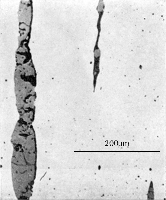
Microstructure of an iron gouge from the Tonglüshan copper-mine site (Ye Jun 1975: 24).

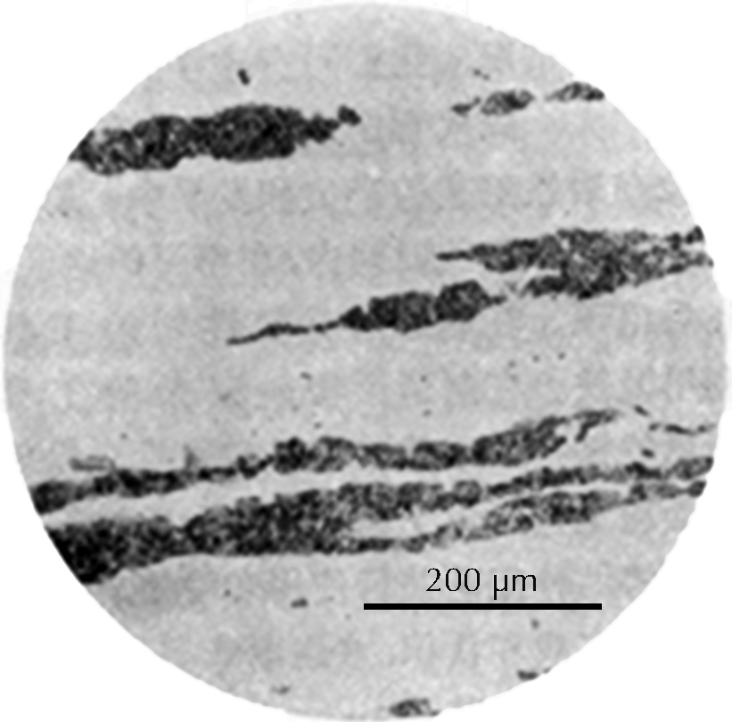
Microstructure of an iron rod from Grave no. 2 at Chengqiao in Luhe County, Jiangsu (Yejin jianshi 1978: 55).
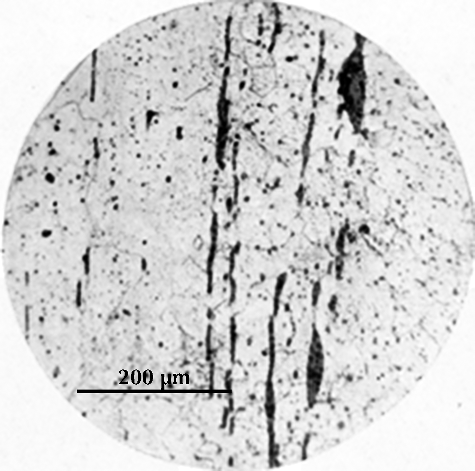
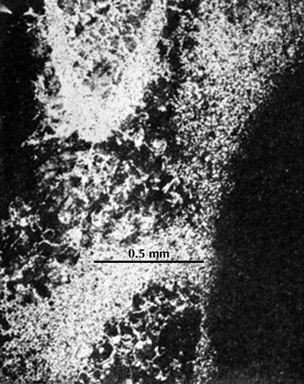
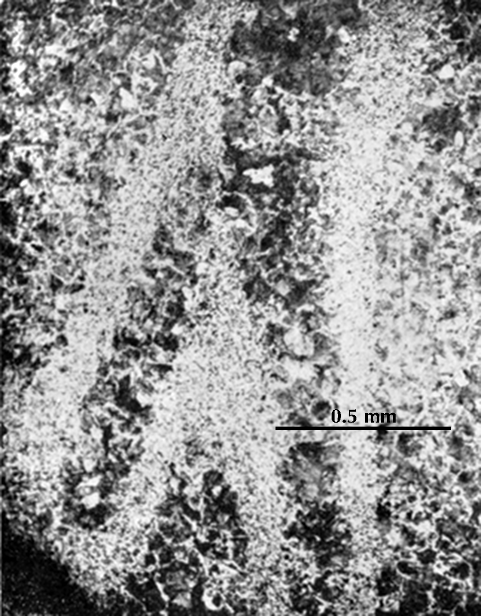
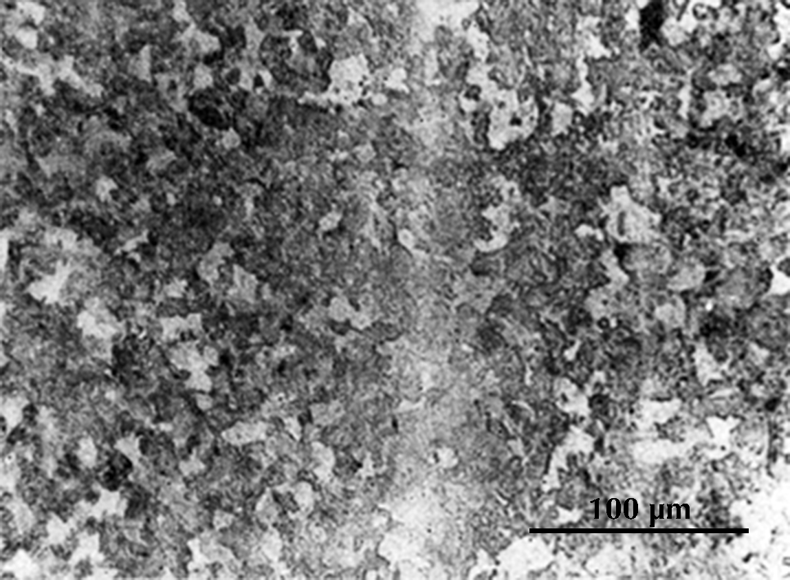
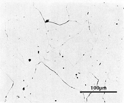
After this grinding and polishing some aspects of the microstructure of the artefact can be seen directly in the microscope, especially the form and distribution of non-metallic inclusions in wrought iron and steel, as can be seen in the three images here on the right. The metallic components of the microstructure of an iron object, however, all look alike after polishing. Most often, therefore, unless one’s only interest is in slag inclusions, it is necessary to etch the polished surface with any of a number of possible etchants. The most important of these is nital, which is a mixture of 1–5% concentrated nitric acid in ethyl alcohol. Picral is similarly a mixture of picric acid in ethyl alcohol. Both of these make the microstructure visible by etching its different components in different ways. Other more specialized etchants are also available. One example is Oberhoffer’s reagent, which makes visible the non-uniform distribution of phosphorus in solid solution in the iron.

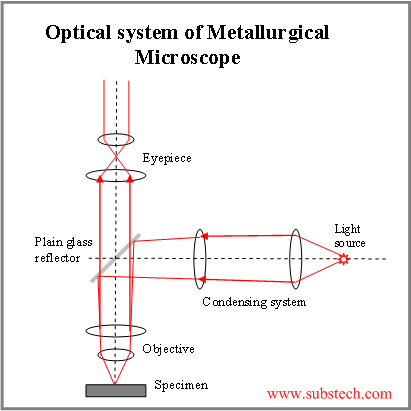
The metallurgical microscope that we use for this work is different from ordinary microscopes. Light must shine directly down on the sample and reflect directly up to the eyepiece. The diagram on the left shows how this is done, with light reflecting downward from a glass reflector, going down to the sample, and then up through the reflector to the eye.
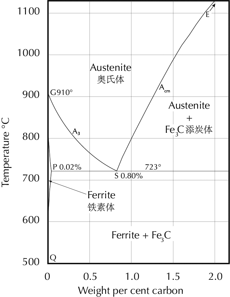
In order to interpret what one sees in the microscope it is necessary to have a firm knowledge of the iron–carbon phase diagram, shown here. Diagrams like this are the fundamental theoretical tool of the metallurgist, and students will find it useful to print this diagram out and have it handy as they read further.

The iron-carbon phase diagram, which gives the atomic state of iron–carbon alloys at different carbon contents and temperatures (after Hansen 1958: 354).
The line ABCD (the liquidus line) gives the temperature above which an iron–carbon alloy is completely molten. As can be seen, this temperature varies considerably with the carbon content. At 4.3% carbon the liquidus temperature is 1153°C, while a steel with 0.5% carbon has a liquidus temperature just under 1500°C. This difference has an enormous importance. High-carbon iron can be cast at temperatures which are easily reached in primitive furnaces, while melting low-carbon iron requires such high temperatures that this has seldom been done in pre-modern times. (There are some exceptions to this statement. They have their own historical importance, but are not of immediate relevance here.) Iron with high carbon content is normally brittle and cannot be worked by a smith; it can only be formed by casting, and is therefore called cast iron. Iron with low carbon content, on the other hand, is so difficult to cast that it has normally (in pre-modern times) been formed only by smithy methods. This has led to the term wrought iron for iron with nearly zero carbon. (The English word wrought is an otherwise obsolete past participle of the transitive verb work.) Steel has a significant amount of carbon but not too much; quantitative definitions vary, but 0.1–2.0% carbon is as good a definition as any.
The present section concerns artefacts of wrought iron or steel which in fact have been wrought, i.e. were formed by smithy methods. In an ancient Chinese context this is a necessary distinction, for in a following section we shall see artefacts which were cast of high-carbon iron and then decarburized to a low carbon content and thus could reasonably be called wrought iron or steel. The normal English term for these is malleable cast iron.
We are therefore not concerned in this chapter with high temperatures or high carbon contents, and we can restrict our attention to ‘the steel corner’, the lower left corner of the iron–carbon phase diagram:
A point to be cleared up at the start is that in metallography, phase is a technical term, not found in all ordinary dictionaries, which is not related to the normal use of the word meaning a stage in a process. A phase in the sense used here is a mechanically distinct homogeneous component of a nonhomogeneous physical–chemical system; in a metallurgical context phases are components of the microstructure with different crystal structures. (The Chinese word is xiang 相.) In the iron–carbon system there are the liquid phase and three solid phases:

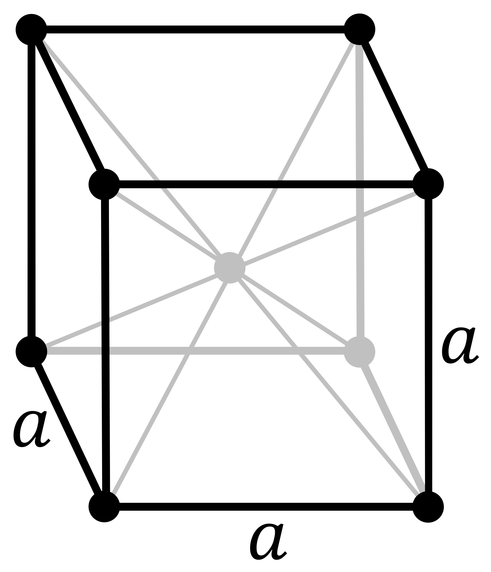
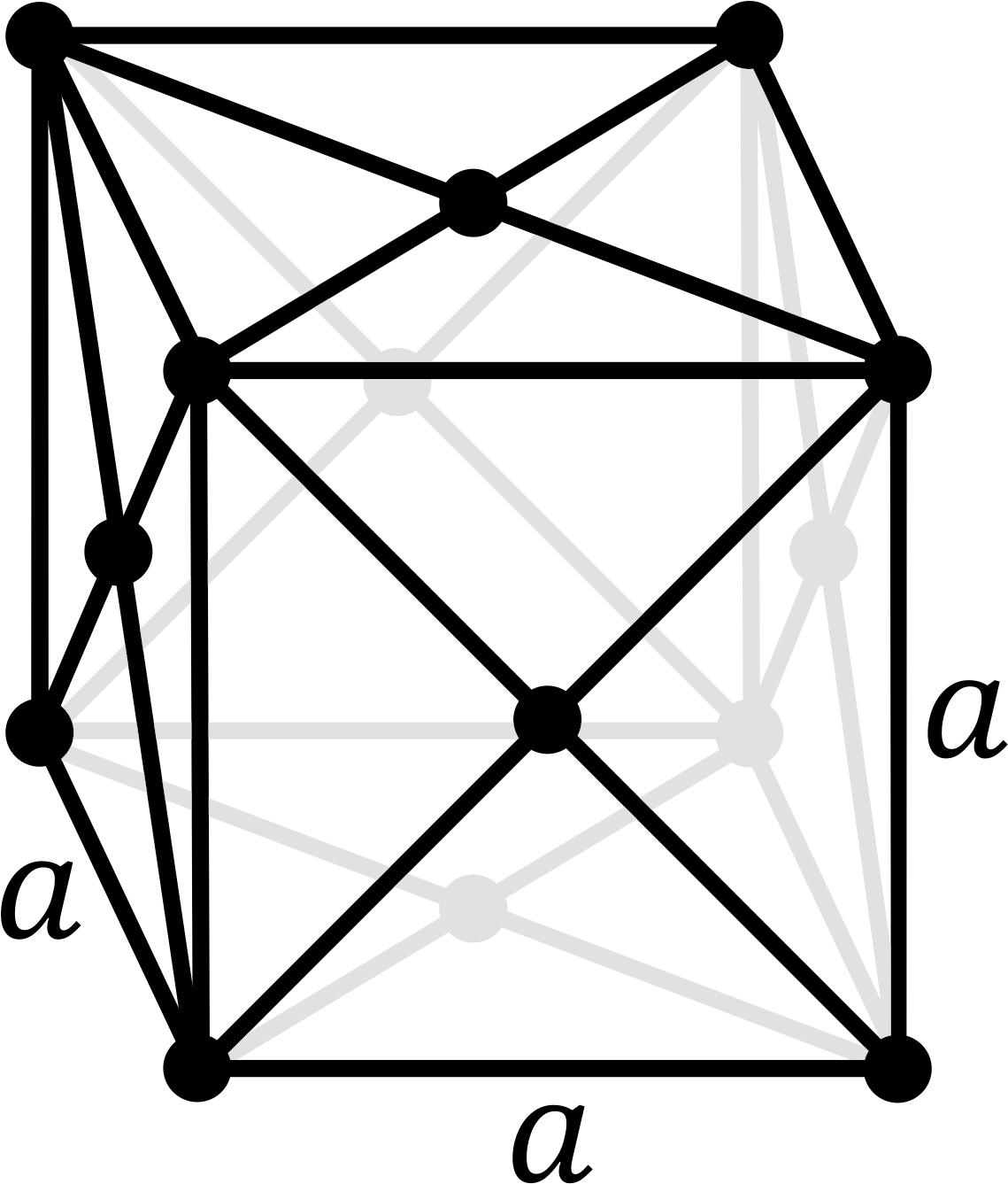
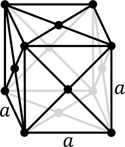
Ferrite: body-centered cubic crystal structure
Austenite: face-centred cubic crystal structure
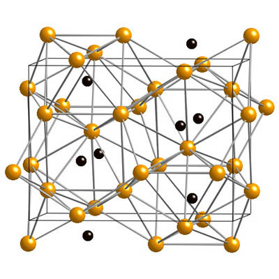
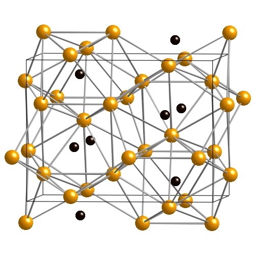
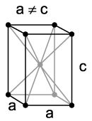
Cementite crystal structure. Yellow: iron atoms; black: carbon atoms.
ferrite, also called α (the Greek letter alpha), with a body-centred cubic crystal structure
austenite, also called γ (the Greek letter gamma), with a face-centred cubic crystal structure
cementite, iron carbide, Fe3C
graphite, elemental carbon (important in cast iron, but very rarely seen in steel)
Cementite has the carbon content determined by its chemical formula Fe3C, i.e. 6.7% by weight. Austenite and ferrite are solid solutions of carbon in iron; the solubility limits depend on the temperature and can be read off the iron–carbon phase diagram. The maximum carbon content of ferrite at different temperatures is given by the line GPQ; the minimum carbon content of austenite is given by NJ (in the full diagram) and GS (also called A3), while the maximum is given by JE and SE (also called Acm).
For example, at a temperature of 800°C the minimum carbon content of austenite is about 0.3% and the maximum is about 1%, while ferrite can have from zero to about 0.01% carbon. An iron–carbon alloy with carbon content between 0.01% and 0.3% must, at 800°C, be composed of two phases: microscopic crystals of ferrite and austenite, for at this temperature there is no homogeneous form of iron which contains an intermediate amount of carbon.
An iron containing 0.2% carbon, heated to 800°C, must at equilibrium consist of two phases: austenite with 0.3% carbon and ferrite with 0.01% carbon. Simple arithmetic shows then that it consists of 66% austenite and 34% ferrite (0.66×0.3 + 0.34×0.01 = 0.2).
If this iron is then slowly cooled to just above 723°C (the A1 line) the same sort of reasoning indicates that it will consist of 23% austenite with 0.8% carbon and 77% ferrite with 0.02% carbon.
Further cooling to just below 723°C brings about a new situation. Nothing happens to the ferrite, but austenite below this temperature is unstable, and must transform to a structure composed of ferrite and cementite. The structure obtained in this transformation depends on the cooling rate: at a typical cooling rate in a smithy, assuming only that the smith is not actively attempting to achieve a very fast or very slow cooling rate, the austenite transforms to pearlite, which is a lamellar structure of ferrite and cementite. The structures which can be obtained by very fast, moderately fast, or very slow cooling will be discussed further below.
After grinding and polishing, followed by etching with either nital or picral, the structures described above show up in the microscope as follows:
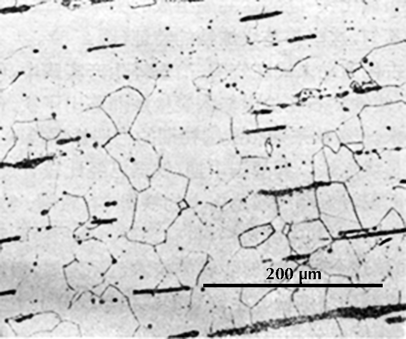
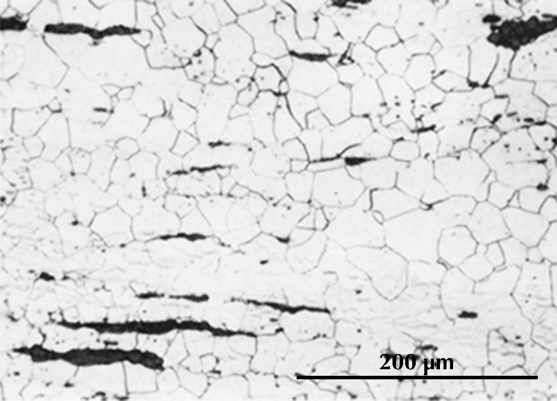
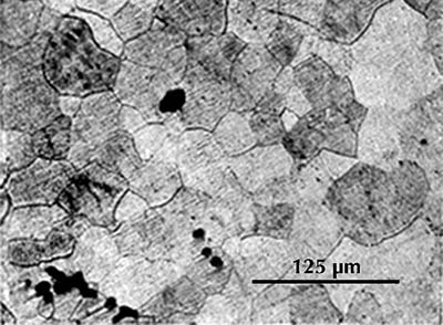
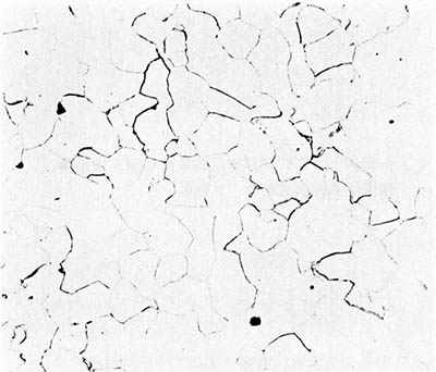
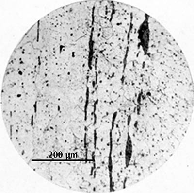
Ferrite etches rather uniformly, but more strongly at grain boundaries (boundaries between individual crystals). The examples here are from iron artefacts with 100% ferrite. (The black streaks in several of these figures are non-metallic slag inclusions.) At room temperature ferrite contains essentially zero carbon.
 |
 |
 |
 |
 |
 |
| Iron rod from Grave no. 2 at Chengqiao in Luhe County, Jiangsu (Yejin jianshi 1978: 55). | Iron plate from the Han ironworks site at Guxingzhen in Zhengzhou, Henan (Kaogu xuebao 1978.1, pl. 2.4. | Leg of an iron brazier from the tomb of Liu Sheng (Mancheng 1980, 2, pl. 253.6) | Armour lamella from the tomb of Liu Sheng (Mancheng 1980, 2, pl. 254.6) | Coffin-nail from a Waring States grave in Qinghe, Hebei (Lu Da 1966, pl. 3.6). | Wrought-iron ring from the Manchi scrap-heap (Wenwu 1976.8, pl. 4.6). |
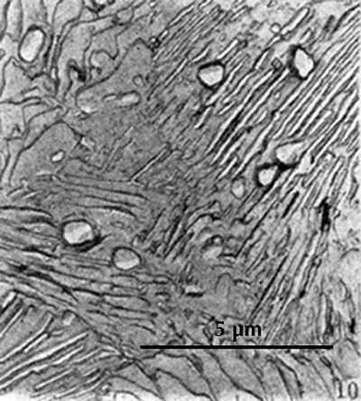
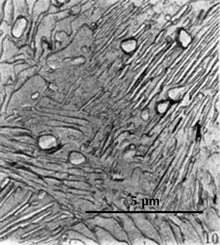
Replica scanning electron micrograph of a sample from a sword from Pankuang (Han Rubin & Ke Jun 1984, pl. 2.10). Etched with nital.
In pearlite the ferrite lamellae etch more deeply than the cementite lamellae, so that a finely corrugated surface results. This corrugation can be seen for example in the electron micrograph here on the right. An optical microscope cannot reach the same magnification and depth of field that are possible in an electron microscope, and here it is usually not possible to distinguish the individual lamellae.

Micrograph of steel with 0.8% C, etched with nital. From George Langford.

The same, in black and white.
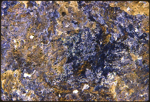
However, when light is reflected from the corrugated surface, interference effects make it seem to be coloured. (Hence the name pearlite, coined in the early days of metallography when optical microscopes were not able to resolve the structure.)

Microstructure of an Eastern Han sword fragment from Jinning, Yunnan (Hua Jueming et al. 1960, pl. 8.2). Etched with 4% nital.
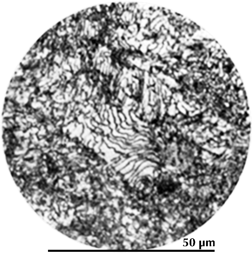
In black-and-white micrographs, pearlite shows up as a grainy black or dark grey. The micrograph on the left shows the microstructure of an iron artefact composed of 100% pearlite. The boundaries of the original austenite grains from which it was formed are visible. (These are often called ‘pearlite colonies’, 群体、集团.)
From this discussion of the iron–carbon phase diagram it can be concluded that an iron artefact with 100% ferrite has essentially zero carbon, while one which is 100% pearlite has about 0.8% carbon. Ferrite is very soft (Vickers hardness HV ca. 90); pearlite is considerably harder (HV ca. 200–300), and a steel with 0.8% carbon is much more suitable for weapons and tools. The Greek writers Polybius and Plutarch tell of Gallic swords that were so soft that they bent in use. These swords undoubtedly had a low carbon content and were composed largely of ferrite; metallographic examination of Celtic swords partially confirms the written account (Pleiner 1993). A similar sword, from Yanxiadu, is described in Kaogu 1975.4: 241–243.
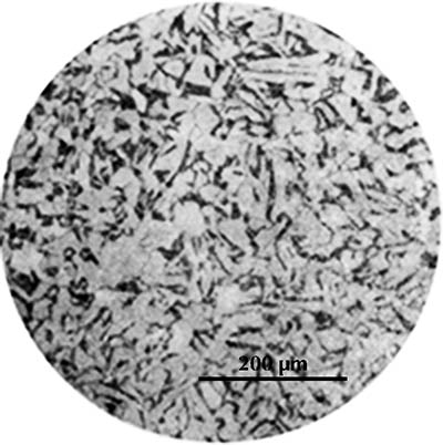
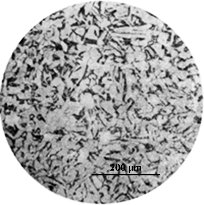
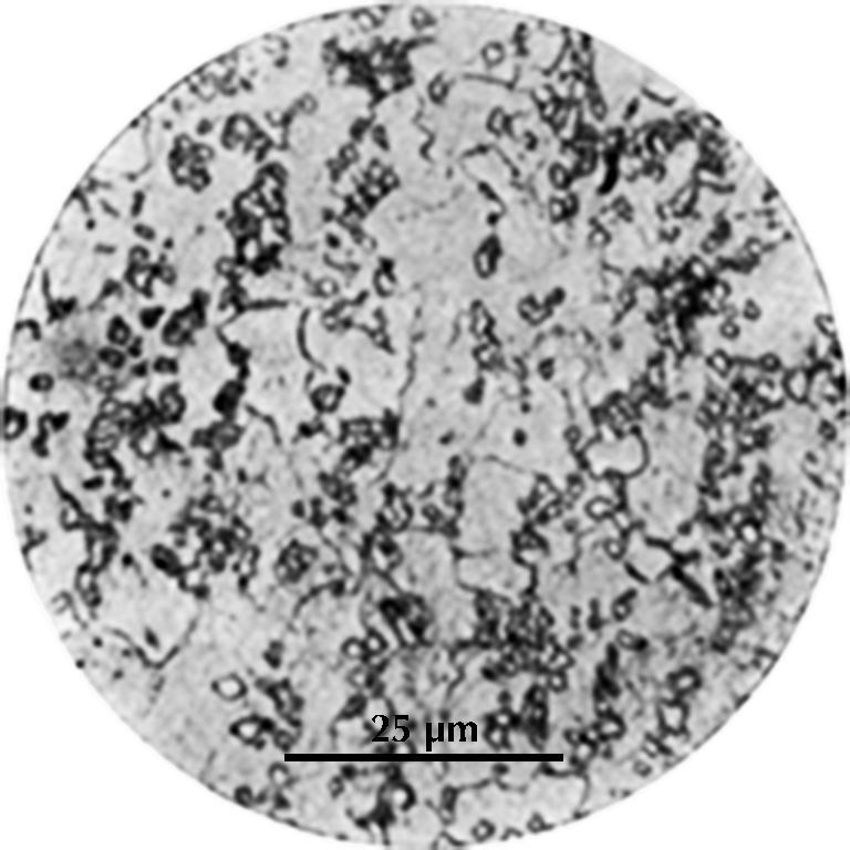
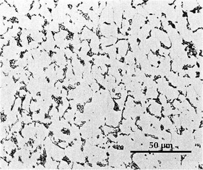
Micrograph from an iron gouge from the Tonglüshan iron-mine site (Ye Jun 1975: 24). Etched with 4% nital.
The micrograph on the right shows the microstructure of an artefact whose chemical analysis is 0.1% carbon. The white areas are ferrite and the dark areas are pearlite. Calculation as before indicates that the microstructure should consist of ca. 18% pearlite with 0.8% carbon and 82% ferrite with zero carbon, and this seems to be the case. It is rare that a metallurgist bothers to analyze an iron artefact for carbon by wet methods as was done here. Usually one simply estimates the carbon content from the microstructure.

Microstructure of a halberd-head from the tomb of Liu Sheng (Mancheng 1980, pl. 261.5).
For example, a halberd-head from Liu Sheng’s tomb in Mancheng is stated to have 0.4% carbon because its microstructure (here on the left) consists of about 50% pearlite in a ferrite matrix. One can be misled using this technique by pearlite whose carbon content is significantly different from 0.8% (see e.g. Brick et al. 1977: 134); but an experienced metallurgist is seldom fooled, and by this means we can investigate variations in carbon content throughout the artefact as opposed to the average carbon content of a large sample.

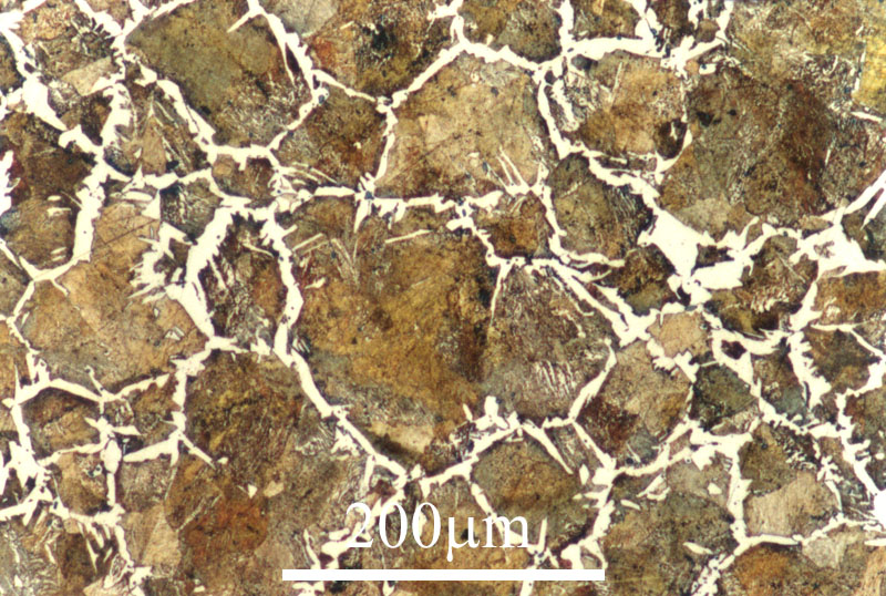
Microstructure of a sample of hypereutectoid steel. From Cambridge University.
So far we have considered eutectoid and hypoeutectoid iron–carbon alloys; that is, iron with 0.8% carbon and with less than 0.8% carbon respectively. Iron–carbon alloys with more than 0.8% carbon are called hypereutectoid. The microstructure of hypereutectoid steel is typically composed of pearlite and what is called reticular cementite. The cementite is distributed along the original austenite grain boundaries and looks rather like a net (reticule means ‘net’).
Welding
Today the word ‘welding’ tends to suggest a welder in a heavy mask with an oxyacetylene torch joining pieces of steel together by locally melting both. That is ‘fusion welding’ (熔焊), which first came into common use in the mid-twentieth century. The pre-modern English term ‘welding’, now often ‘forge welding’ (锻接), refers to an utterly different technique. Two pieces of iron to be welded together are heated in the forge hearth to a very high temperature, typically in the range 1300–1400°C (Shrager 1969: 38), but still far below the melting point of the iron. When they are well heated the two are taken from the hearth and hammered together on the anvil. If this is done correctly the two pieces are perfectly joined together and now form one piece of metal.
When a smith has heated a piece of iron to welding temperature he may very well point out to visitors what seems to be a fluid on the surface of the iron and say that the iron is now hot enough to weld, for it is molten on the surface. Actually it is not the iron which is molten but the slag, a mixture of FeO (iron oxide), SiO2, and perhaps some other components. At the high temperatures employed it is unavoidable that some of the iron burns to FeO, which has a high melting point, 1369°C. If the slag is not liquid, it will act as a barrier between the pieces of metal, and the welding will not succeed. A mixture of FeO and SiO2 can have a much lower melting point, as low as 1177°C, so the smith may cast sand (which is quartz, SiO2) on the two surfaces to be welded together. The liquid slag layer also protects the iron from oxidation and so facilitates welding. Some slag will inevitably be trapped between the welded surfaces, though the smith will work hard to keep this to a minimum.
Slag inclusions introduced in welding are not the only ones which will be found in the artefacts. Regardless of how pre-modern wrought iron was produced, whether directly from a bloomery or indirectly by fining or puddling of cast iron, there would virtually always be some slag inclusions in the raw material that the smith started with. The black streaks or blotches seen in most of the micrographs on this page are usually slag inclusions. Study of the form, distribution, and chemical composition of these inclusions can tell a great deal about how an artefact was made.
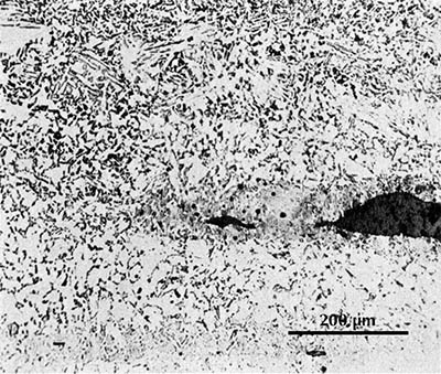
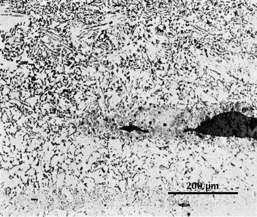
Microstructure of a gold-inlaid knife from Mancheng (Mancheng 1980, pl. 256.2).
There are two ways in which a weld can be recognized in the microstructure. Often the slag inclusions introduced in the welding process will appear neatly lined up in a row and be distinct in appearance from other slag inclusions in the iron. The two original pieces of iron may also – incidentally or intentionally – be different in carbon content or in the content of some other alloying element. A weld can be seen in the micrograph here on the right. The microstructure is composed of ferrite and pearlite, together with some slag inclusions. In the upper part of the micrograph there is distinctly more pearlite than in the lower part, and there is a fairly sharp boundary between these zones of different carbon content. Exactly at this boundary is a large slag inclusion; it must have been introduced by the smith in welding together two pieces of iron with different carbon contents.
Often a smith must weld several pieces of iron together simply in order to obtain a piece of the necessary size for some artefact, but welding has other purposes as well. The smith may for example weld a steel cutting edge onto a softer iron implement.
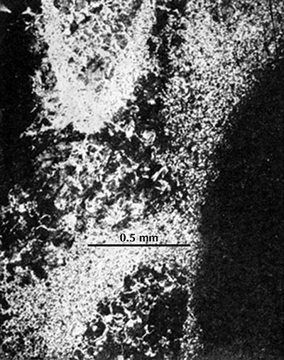
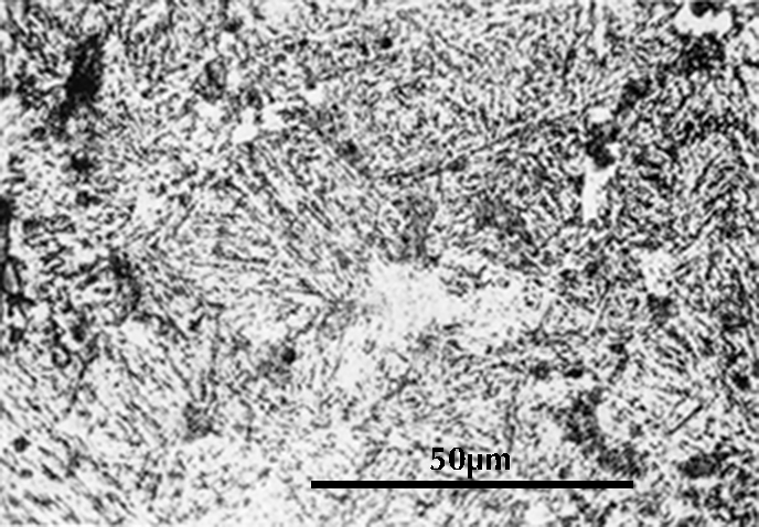
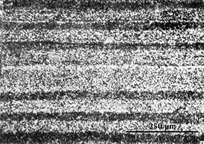
Two micrographs from a sword fragment from Yan Xiadu (Li Zhong 1975, pl. 2.11–12).
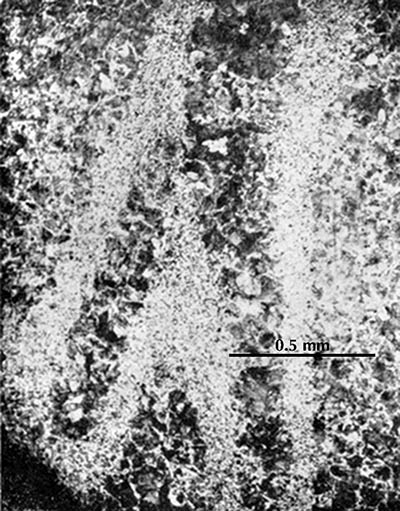
The two micrographs on the right show the microstructure of a sword from the third century BCE The white areas are ferrite and the dark areas are pearlite. It can be seen that the carbon content varies considerably through the artefact. The researchers conclude that the sword was made of a number of pieces of iron which were hammered out to thin plates and then surface-carburized (by cementation) so that they had a high carbon content at the surface and a much lower carbon content in the core. These were then folded and welded together in intricate ways to make the sword. This much is clear enough, but without further studies it is not possible to say much more. We should like in particular to know whether the smith folded and combined the steel plates randomly or with some definite plan.
In another sword, heterogeneous pieces of iron are combined in a more obvious pattern. Near the surface of the blade the microstructure is as on the left below, with alternating layers of higher- and lower-carbon steel. At the centre it is as on the right, a homogeneous steel with ca. 0.8% carbon.
 |
 |
Micrographs of a sample from a sword from Pankuang in Tongshan, Jiangsu (Han Rubin & Ke Jun 1984, pl. 1.4–6).
Quench-hardening
A famous passage in Homer’s Odyssey, often quoted in histories of metallurgy, must be quoted again here. Odysseus has plunged a burning wooden spike into the eye of the Kyklops:
Just as a smith dips a great axe or adze in cold water, treating it so that it cries, for the strength of the iron comes of this, thus hissed his eye around the olive stake.
The quench-hardening technique, in which a steel artefact is heated to a high temperature (typically 800–900°C, a red heat) and then suddenly cooled in water or another liquid, is certainly one of the most spectacular of the arts of the smith. From a moderately hard microstructure the smith obtains one which is extraordinarily hard and can take and hold a very sharp edge, but is also very brittle; it can shatter like glass, and is sometimes said to be ‘glass-hard’. The hardness and brittleness can be adjusted by reheating to a lower temperature (200–600°C). This process, applied to a quench-hardened iron artefact, is called tempering, and it results in a structure which is less hard but also less brittle.

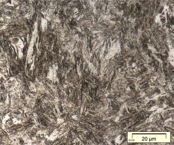
Martensite: body-centred tetragonal crystal structure
I have already noted above that when austenite is cooled below 723°C it must transform to another structure. At normal cooling rates it transforms to the lamellar two-phase structure called pearlite. At very fast cooling rates it transforms instead to martensite, which is a body-centred tetragonal crystal structure with carbon in solid solution. Martensite is extremely hard and brittle. When polished and etched it appears in the microscope as an indistinct pattern of needles or plates. Here are two examples:
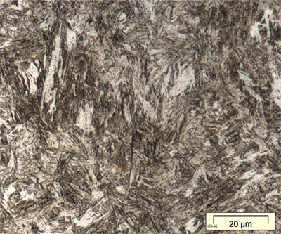 |
 |
| Martensitic sample, from Naderi & Bleck. | Sword fragment from Sandaohao in Liaoyang, Liaoning (Hua Jueming et al. 1986, pl. 3.6. |
Tempering the martensite causes some of the carbon in solid solution to precipitate as microscopic or submicroscopic spheroids of cementite. The resulting structure is less hard and less brittle than untempered martensite.
Besides pearlite and martensite there is another structure, which can be formed at an intermediate cooling rate, bainite. When a fairly thick steel artefact is quench-hardened it may well happen that martensite forms only near the surface. Further inward the iron cools more slowly, and bainite forms instead.
A number of early and now obsolete theories on the hardening of steel have left their mark on the terminology used in describing microstructures. Pearlite, martensite, and bainite have survived as internationally approved terms; in addition upper bainite and lower bainite are approved terms for bainite formed by transformation at high and low temperatures respectively, which look rather different in a polished and etched section. Troostite is an almost obsolete term for an extremely fine pearlite formed at intermediate cooling rates which formerly (before the use of the electron microscope) was believed to be a single-phase structure (Sauveur 1920: 285–289; Tylecote & Gilmour 1986: 5). Another obsolete term is sorbite, which seems also to refer to a form of fine pearlite (Sauveur 1920: 225–226; 289–291). Both terms were ambiguous, and could also refer to different forms of tempered martensite (Metals handbook 1939: 9, 10), apparently because of some early theoretical confusion. The term ‘troostite’ (Chinese qushiti 屈氏体) is often seen, both east and west, in metallographic reports on ancient artefacts. ‘Sorbite’ (suoshiti 索氏体) is also seen quite often in Chinese reports. In addition, the peculiar and self-contradictory term ‘carbon-free bainite’ (wutan beishiti 无碳贝氏体) is sometimes used here. It seems to mean the same as ‘lower bainite’.
Work-hardening
Another method of significantly increasing the hardness of iron (or any metal) is to hammer it while cold. The smiths I met in Kaifeng used a well-developed work-hardening technique; whether work-hardening has been widely used among Chinese smiths I cannot be sure, but it seems likely. If so, this difference between the traditional practices of Chinese and European smiths might be explained by the extreme shortage of fuel in China in recent centuries.
(Mancheng 1980, pl. 253.5)
I know of one ancient Chinese artefact which is work-hardened: a small chisel of the second century BCE. The ferrite grains are said to be elongated to an extent that indicates a cold deformation of ca. 30%; unfortunately the published micrograph (here on the right) is poorly reproduced, and it is impossible to see the ferrite grain boundaries, but the pearlite in the microstructure is obviously deformed. The carbon content is estimated at 0.25%, and this steel would normally have a hardness a bit over 100 HV, at the most perhaps 150 HV; but cold deformation has increased the hardness at the cutting edge to as much as 250 HV. One would think that a chisel ought to have a much higher hardness; the cutting edge of a modern chisel usually has a hardness in the range 450–600 HV. Tylecote & Gilmour (1986: 69) found that most British chisels of Roman times have similarly low hardness. A smith who was sufficiently skilled to make a perfect chisel would have been more inclined to use his skill making swords and other products with a higher value than common tools, and an acceptable chisel could be made by work-hardening a low-carbon steel.
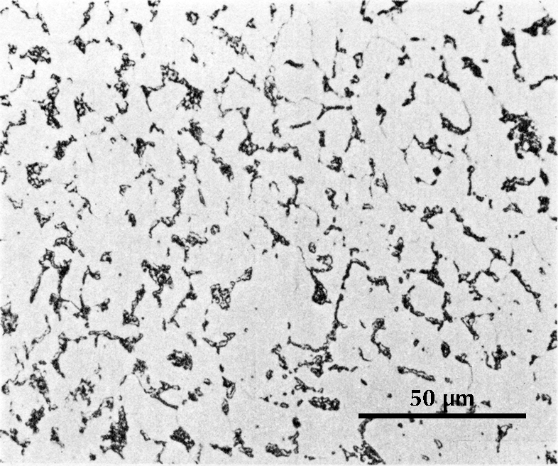
Softening treatments
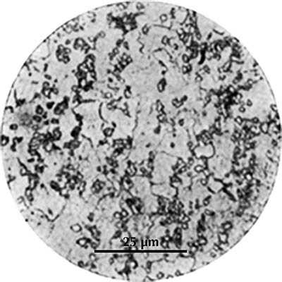
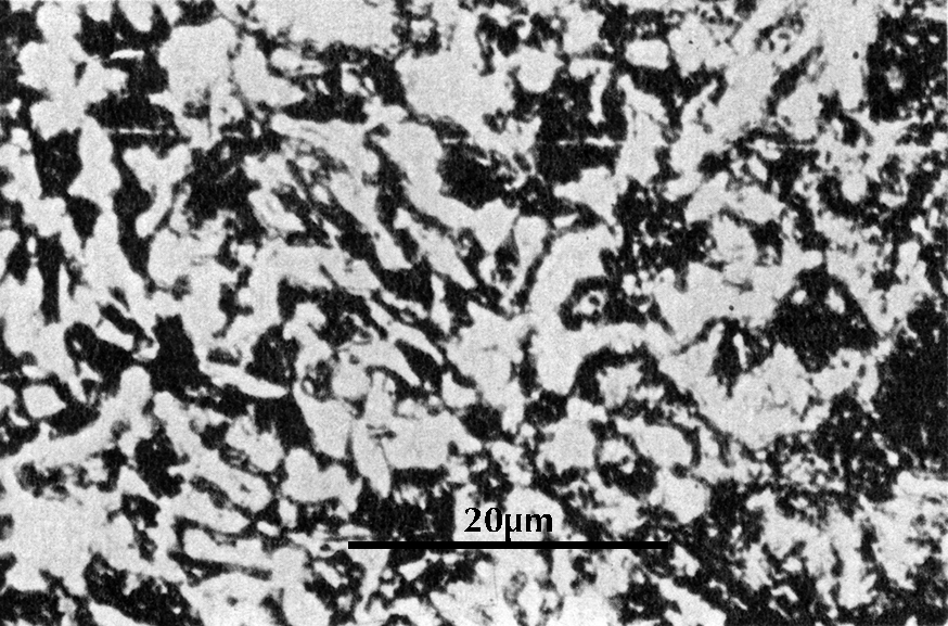
Microstructure of a short sword from Yangjiashan in Changsha, Hunan (Chen Weimin 1978: 48).
A sword from a pre-Han grave in Changsha, Hunan, has a surprising microstructure. It appears to be made of steel with 0.5% carbon, which could by appropriate heat treatment be made very hard and strong. In fact, however, the sword has the softest microstructure that such a steel can have, consisting of cementite spheroids in a ferrite matrix (micrograph here on the right).
A structure like this can be produced in either of two ways. One is by excessive tempering of a quench-hardened artefact. When martensite is tempered at a temperature just under 723°C for several hours the entire carbon content precipitates as cementite and the result is a structure something like that seen here, with cementite spheroids in a ferrite matrix (see e.g. Brick 1969: 152–155). It is possible that the sword was first quench-hardened and then completely softened by an excessive tempering, but this seems unlikely here.
Another possibility is suggested by a process used in modern industry to soften steel in preparation for machining. Steel with a pearlitic structure is heated to a temperature just above 723°C, then held for a period of hours at a temperature just below 723°C. The result is the same sort of structure seen here (Honda & Saitō 1920). The process can be accelerated by a preliminary cold deformation, as also by a ‘pendulum’ anneal in a program-controlled furnace, with the temperature swinging between just above and just below 723°C (Offer-Andersen 1984: 375–378).
Now if a smith uses an insufficiently high temperature in hot-working an artefact, something like these same conditions will result. At such temperatures pearlite may not entirely transform to austenite in the time available, and hammering will have much the same effect as cold hammering (breaking the cementite lamellae in pearlite). Forming the artefact will also be more difficult, and therefore require more time at temperature, than at higher temperatures. Even if the temperature of the part of the artefact being worked is considerably above 723°C, nearby parts may very well oscillate above and below this temperature in the course of repeated heating and hammering.
A number of edge tools and weapons examined by Tylecote and Gilmour (1986) were found to contain partially or entirely spheroidized pearlite. All seem to be explainable in the way suggested here: the artefacts were forged at low temperatures, perhaps in the range 800–900°C, and this resulted in a softer microstructure than intended.
References
Brick, Robert M. (et al.) 1977. Structure and properties of engineering materials. 4th edn. New York: McGraw–Hill.
Chen Weimin 陈慰民. 1978. ‘Changsha xin faxian Chunqiu wanqi de gang jian he tieqi’ 长沙新发现春秋晚期的钢剑和铁器 (A steel sword and some iron artifacts of the late Spring and Autumn period discovered in Changsha, Hunan). Wenwu 文物 1978.10: 44–48.
Guyan, Walther Ulrich (ed.). 1967. Vita pro ferro: Festschrift für Robert Durrer zum 75. Geburtstag am 18. November 1965. Schaffhausen. n.d. [ca. 1967].
Han Rubin 韓汝玢, and Ke Jun 柯俊. 1984. ‘Zhongguo gudai de bailian gang’ 中国古代的百炼钢 (The ‘hundredfold refined’ steel of ancient China). Ziran kexueshi yanjiu 自然科学史研究 (‘Studies in the history of natural sciences’) 3.4: 316–320 + pl. 1–2.
Hansen, Max. 1958. Constitution of binary alloys. 2nd edn. New York: McGraw-Hill.
Honda, Kōtarō, and Seitō Saitō. 1920. ‘On the formation of spheroidal cementite’. Journal of the Iron and Steel Institute (London) 102.2: 261–269.
Hua Jueming 华觉明, Yang Gen 杨根, and Liu Enzhu 刘恩珠. 1960. ‘Zhanguo Liang Han tieqi de jinxiangxue kaocha chubu baogao’ 战国两汉铁器的金相学考查初步报告 (Preliminary report on metallographic examination of some Warring States and Han period iron artifacts). Kaogu xuebao 考古學報 (‘Acta archaeologia Sinica’) 1960.1: 73–88 + pl. 1–8.
Hua Jueming 华觉明 (et al.). 1986. Zhongguo yezhu shi lunji 中国冶铸史论集 (Essays on the history of metallurgy in China). Beijing: Wenwu Chubanshe.
Kaogu xuebao 考古学报. 1978.1. ‘Henan Handai yetie jishu chutan’ 河南汉代冶铁技术初探 (‘The iron and steel making techniques of the Han dynasty in Henan’). Kaogu xuebao 考古学报 1978.1: 1–24 + pl. 1–2.
Kaogu 考古. 1975.4. ‘Yixian Yanxiadu 44 hao muzang tieqi jinxiang kaocha chubu baogao’ 易县燕下都44号墓葬铁器金相考察初步报告 (Preliminary report on metallographic examination of iron artifacts from grave no. M44 at the Yanxiadu site in Yixian County, Hebei). Kaogu 考古 (‘Archaeology’) 1975.4: 241–243.
Lu Da 陆达. 1966. ‘Zhongguo gudai de yetie jishu’ 中国古代的冶铁技术 (‘Iron making in ancient China’). Jinshu xuebao 金属学报 (‘Acta metallurgica Sinica’) 9.1: 1–3 + pl. 1–4. English abstract p. 3. Full Chinese text + German translation, ‘Die uralte Technik der Eisenherstellung in China’, Guyan 1967: 63–70.
Mancheng. 1980. Mancheng Han mu fajue baogao 滿城漢墓發掘報告 〔上 下〕 (‘Excavation of the Han tombs at Man-ch’êng’). (Zhongguo tianye kaogu baogao ji: Kaoguxue zhuankan, D.20 中国田野考古报告集考古学专刊) Beijing: Wenwu Chubanshe.
Metals handbook. 1939 edn. Cleveland, Ohio: American Society for Metals.
Zhongguo yejin jianshi 中國冶金簡史. 1978. (A concise history of metallurgy in China). Beijing: Kexue Chubanshe.
Offer Andersen, K., Celia Juhl, Conrad Vogel, and Erik Nielsen. 1984. Metallurgi for ingeniører. 5th edn. København: Akademisk Forlag.
Pleiner, Radomír. 1993. The Celtic sword. Oxford: Clarendon Press.
Sauveur, Albert. 1920. The metallography and heat treatment of iron and steel. 2nd edn. Cambridge, Mass.: Sauveur and Boylston Mechanical Engineers.
Smith, Cyril Stanley. 1988. A history of metallography: The development of ideas on the structure of metals before 1890. Rev. edn. Cambridge, Mass.: MIT Press. Orig. University of Chicago Press, 1960.
Tite, M. S. 1972. Methods of physical examination in archaeology. London & New York: Seminar Press.
Tylecote, R. F. , and Brian J. J. Gilmour. 1986. The metallography of early ferrous edge tools and edged weapons. (BAR British series 155). Oxford: B. A. R.
Wang Lan 王岚, Yang Ping 杨平, and Li Changrong 李长荣. 2013. Jinxiang shiyan jishu 金相实验技术 (Techniques of metallographic examination). 2nd ed. 第二版. Beijing: Yejin Gongye Chubanshe.
Wenwu 文物. 1976.8. ‘Henan Mianchi jiaocang tieqi jianyan baogao’ 河南渑池窖藏铁器检验报告 (Metallographic examination of iron objects from a trove in Mianchi County, Henan). Wenwu 文物 1976.8: 52–58 + pl. 4.
Ye Jun 冶軍. 1975. ‘Tonglüshan gu kuangjing yizhi chutu tiezhi ji tongzhi gongju de chubu jianding’ 铜绿山古矿井遗址 出土铁制及铜制工具的初步鉴定 (Preliminary investigation of iron and bronze artifacts from the ancient mining site at Tonglüshan in Daye County, Hubei). Wenwu 文物 1975.2: 19–25.
Last edited by DBW 27 February 2023
Stylistic changes 7 June 2024